
Dilatable balloon implant

A technology of implants and airbags, applied in joint implants, joint implants, spinal implants, etc., can solve problems such as carry away, vertebrae cannot stand upright, and blockage, so as to reduce the risk of sclerosis and achieve good therapeutic effects. Effect

Inactive Publication Date: 2005-08-31
微治疗发展研究中心有限公司
View PDF0 Cites 12 Cited by
  • Summary
  • Abstract
  • Description
  • Claims
  • Application Information

AI Technical Summary

Problems solved by technology

The drawback of this method is that the vertebrae cannot stand upright until stabilized
Also, there is a risk that the filler will flow out of the vertebral cavity and into the body with this method
[0003] In addition, fillers may enter the spinal canal, intervertebral foramina, or venous plexus of the vertebrae and block them or be carried away by the blood flow, causing an embolism or infarction
This method also has a special problem: if the viscosity of the filler is too low, the risk of the filler leaking out of the vertebral cavity increases, while when the viscosity is too high, the filler hardens too quickly, leading to incomplete filling. full
This method prolongs the surgical procedure by requiring removal of the balloon catheter, and there is a risk that tension in the back muscles will invalidate the previously accomplished erection
In addition, kyphoplasty does not completely prevent fillers from entering the spinal canal, foramen, or venous plexus

Method used


Image

  • Dilatable balloon implant
  • Dilatable balloon implant
  • Dilatable balloon implant

Examples


Embodiment Construction

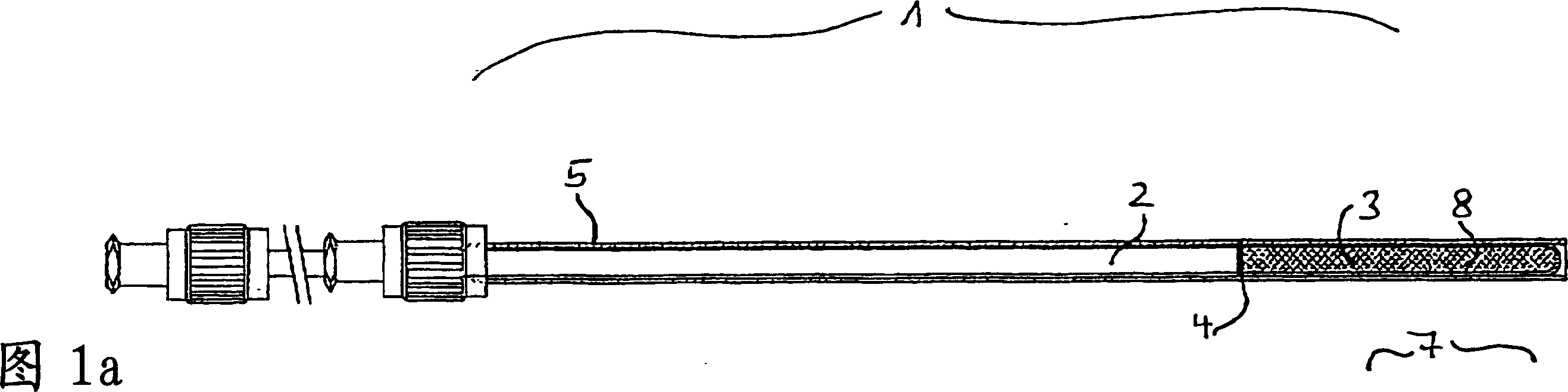
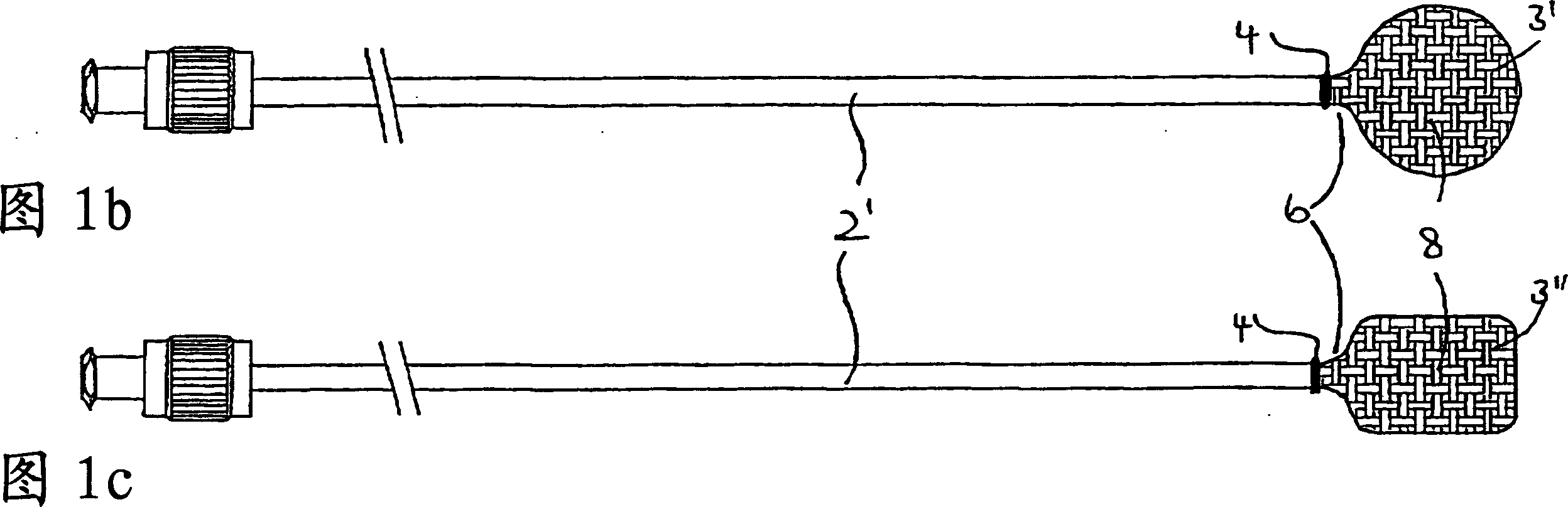
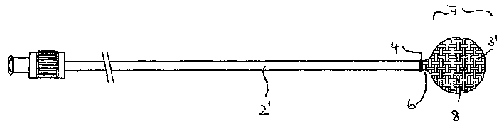
[0039] The vertebroplasty device 1 shown in FIG. 1a includes an introduction sleeve 2 and an inflatable balloon implant 3. At the end of the introduction sleeve 2, the balloon implant 3 is connected to the outer wall of the introduction sleeve 2 in a form-fitting manner by thermoforming. In order to provide additional safety, the connection is reinforced by a clamp ring designed to block the ring 4 and act on the outer periphery of the introduction sleeve 2 to prevent any movement in the direction of the end.

[0040] After using a known technique such as a trocar to establish a percutaneous passage and open the vertebrae, the introduction aid 5, such as a hollow needle of a trocar, is moved up to the vertebral opening, and the balloon implant 3 is deflated. Into the vertebral cavity under the state.

[0041] In this X-ray controlled operation, the introduction sleeve 2 is first moved up to the vertebral opening. Then, the airbag is introduced into the cavity by moving the introdu...


PUM


Abstract

The invention relates to a dilatable balloon implant (3), which is configure d with a limited permeability to liquid. The invention also relates to a vertebroplasty device comprising a balloon implant (3) with a limited permeability to liquid, which is connected to the distal end of an introduction sleeve (2), in such a way that the interior of said implant communicates with the introduction sleeve.

Description

Technical field [0001] The invention relates to an inflatable airbag implant. The invention also relates to a device for placing such an implant in a bone cavity. Background technique [0002] The known method of treating vertebral fractures (especially vertebral fractures caused by osteoporosis in bone tissues) is to directly fill bone cement or other fillers into the vertebrae through percutaneous channels to stabilize the vertebrae (vertebral bones). Body plasty). The disadvantage of this method is that the vertebrae cannot stand upright before being stabilized. Moreover, this method has the risk that the filler flows out of the vertebral cavity and enters the body. [0003] In addition, the filler may enter the spinal canal, intervertebral foramen, or venous plexus of the vertebrae and block them or be carried away by the bloodstream, causing emboli or infarction. This method also has a special problem: if the viscosity of the filling is too low, the risk of the filling flowi...

Claims


Application Information

Patent Timeline
Patent Type & Authority Applications(China)
IPC IPC(8): A61B17/56A61B17/88A61F2/00A61F2/30A61F2/44A61F2/46
CPCA61F2210/0057A61F2230/0082A61F2002/30069A61F2002/30271A61F2002/30561A61F2002/30589A61B17/7098A61F2002/4629A61F2002/4627A61F2/4601A61F2310/00353A61F2/4611A61F2002/30784A61F2002/30074A61F2/30723A61F2002/3025A61F2002/4635A61F2/441A61F2002/30914A61F2002/4495A61F2230/0071A61F2002/30242A61F2002/30593A61F2002/30261
Inventor 迪特里希·格勒内迈尔马丁·德利于尔根·斯佩达约恩·里克特
Owner 微治疗发展研究中心有限公司
Learn More