Method for delivery of substrate to film forming device for disk-like substrate, substrate delivery mechanism and substrate holder used for the method, and method of manufacturing disk-like recording

A technology for substrates and brackets, applied in the manufacture of optical record carriers, optical recording/reproduction, optical record carriers, etc., can solve problems such as warping of the central part of the substrate

Inactive Publication Date: 2005-08-31
TDK CORPARATION
View PDF0 Cites 6 Cited by
  • Summary
  • Abstract
  • Description
  • Claims
  • Application Information

AI Technical Summary

Problems solved by technology

However, as described above, the thin film formation process using a sputtering device and by using such a struc

Method used


Image

  • Method for delivery of substrate to film forming device for disk-like substrate, substrate delivery mechanism and substrate holder used for the method, and method of manufacturing disk-like recording
  • Method for delivery of substrate to film forming device for disk-like substrate, substrate delivery mechanism and substrate holder used for the method, and method of manufacturing disk-like recording
  • Method for delivery of substrate to film forming device for disk-like substrate, substrate delivery mechanism and substrate holder used for the method, and method of manufacturing disk-like recording

Examples


no. 1 example

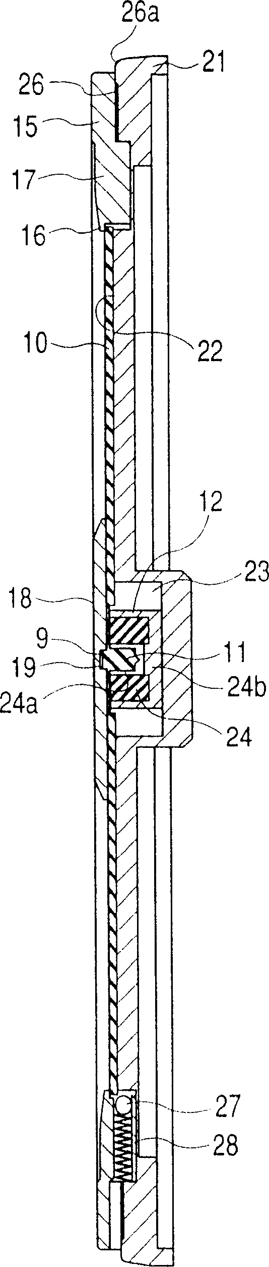
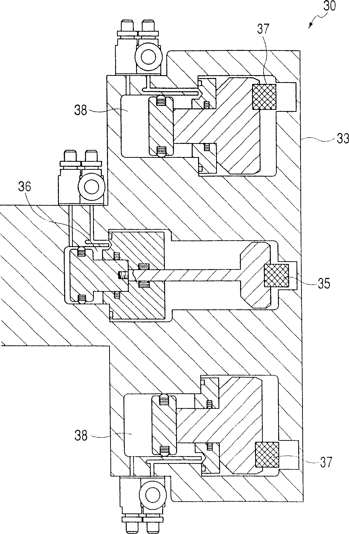
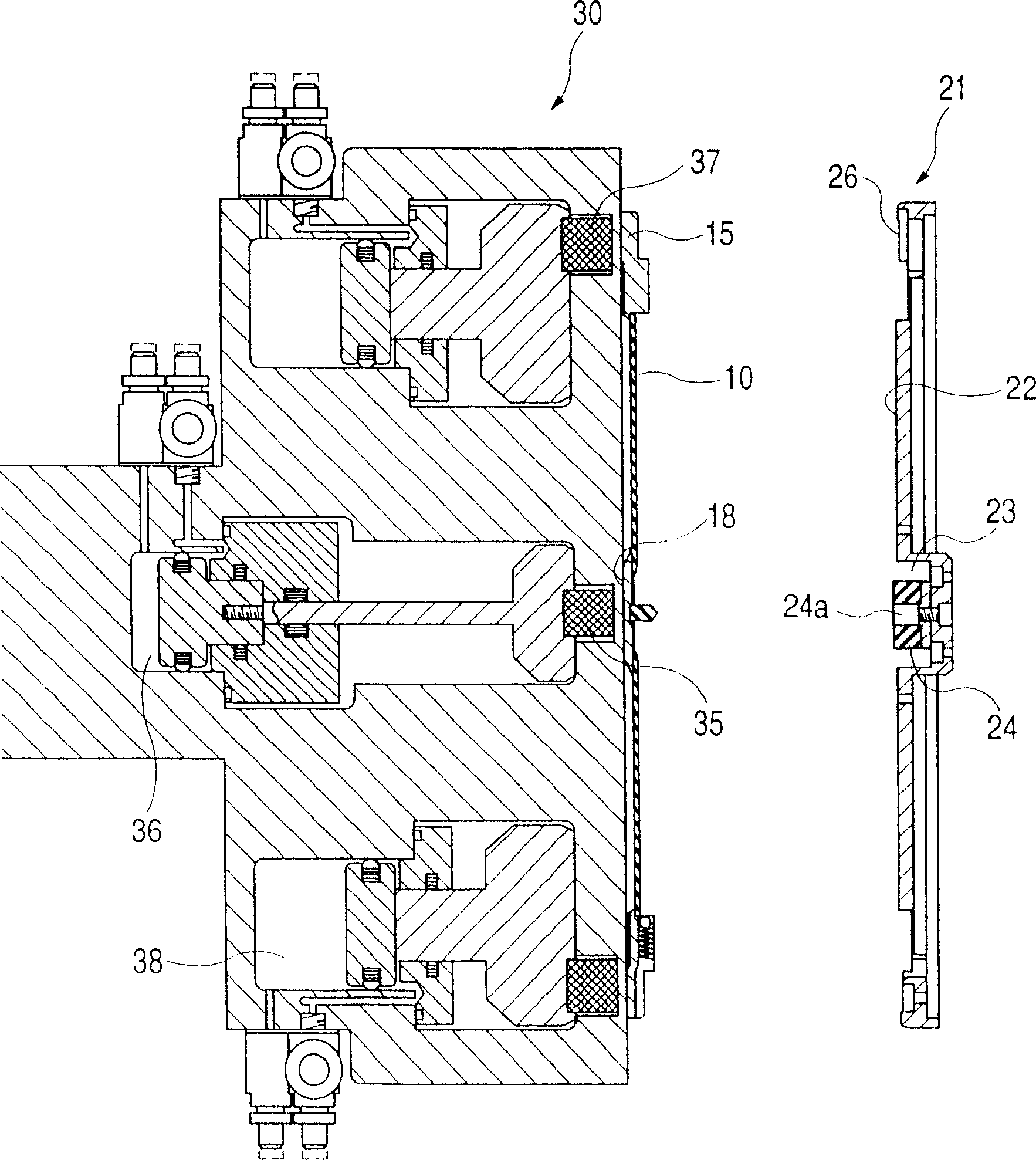
[0030] Hereinafter, a substrate holder, a substrate transfer mechanism, etc. according to a first embodiment of the present invention will be described in detail. figure 1 is a schematic cross-sectional view showing the substrate carrier, the substrate held by the substrate carrier, an outer mask and an inner mask, the substrate carrier can be held with the substrate by the transfer mechanism together and actually hold the substrate during thin film formation using a sputtering device or the like. also, figure 2 is a schematic cross-sectional view of an airside transfer arm with the substrate transfer mechanism positioned substantially opposite the substrate carrier holding the substrate and between the substrate transfer mechanism and the substrate carrier The substrate and the mask are passed between racks. also, Figures 3 to 6 are schematic cross-sectional views each showing how substrate transfer is performed according to the above structure.

[0031] A substrate 10 ...

no. 2 example

[0050] Figure 7 is a schematic sectional view of a substrate carrier according to a second embodiment of the present invention, and a substrate held by the carrier, an outer mask, and an inner mask. The substrate holder can be held together with the substrate by the transfer mechanism according to the present invention, and actually holds the substrate during thin film formation using a sputtering device or the like. It should be noted that, except for the substrate transfer mechanism, the configuration of this embodiment is almost the same as that of the first embodiment, so description thereof is omitted here.

[0051] The difference between the substrate holder of this embodiment and the substrate holder of the first embodiment is that an elastic member is provided on the bottom surface of the magnet 24 . Therefore, the following description focuses only on this point. In the first embodiment, the magnet 24 has a screw hole or the like (not shown) on the bottom surface 2...


PUM


Abstract

The present invention relates to a method of delivering a substrate capable of holding the disk-like substrate without a center hole in the air and capable of easily transferring the substrate to a spattering device. In the present invention, a projected part is provided at both face center parts of the disk-like substrate and the substrate formed integrally with an outer mask and an inner mask covering the outer peripheral end part and the center part thereof for transportation, the inner mask and the outer mask are held by a magnetic force in a delivery mechanism, the inner and outer masks are held simultaneously by a magnetic force also in a substrate holder for receiving the substrate and, at the time of delivery, the magnetic force on a delivery mechanism side is reduced.

Description

technical field [0001] The present invention relates to a thin film forming apparatus for forming a thin film on a disk-shaped substrate. More particularly, the present invention relates to a method of transferring a disk-shaped substrate used in the apparatus to the apparatus, and a mechanism used in the method. In addition, the present invention also relates to a so-called substrate carrier used with the mechanism, and a disc-shaped recording medium manufacturing method for manufacturing a disc-shaped recording medium such as a so-called optical disc by using the mechanism. technical background [0002] Examples of recording media manufactured by forming various types of thin films on disc-shaped substrates, especially recording media having a disc-like shape include CD discs such as CD, CD-R or CD-RW and DVD discs Optical discs such as DVD-ROM or DVD-R; magneto-optical discs such as MO or MD; and various other types of discs. These discs are manufactured, for example, b...

Claims


Application Information

Patent Timeline
IPC IPC(8): C23C14/04C23C14/50G11B7/26
CPCG11B7/266G11B7/265C23C14/042C23C14/50
Inventor 越川政人渡边英昭
Owner TDK CORPARATION
Why Eureka
Try Eureka