Cask and method of producing the same
A shielding tank, one party's technology, applied in the field of shielding tanks, can solve the problems of undisclosed manufacturing methods and unclear realization
- Summary
- Abstract
- Description
- Claims
- Application Information
AI Technical Summary
Problems solved by technology
Method used
Image
Examples
Embodiment approach 1
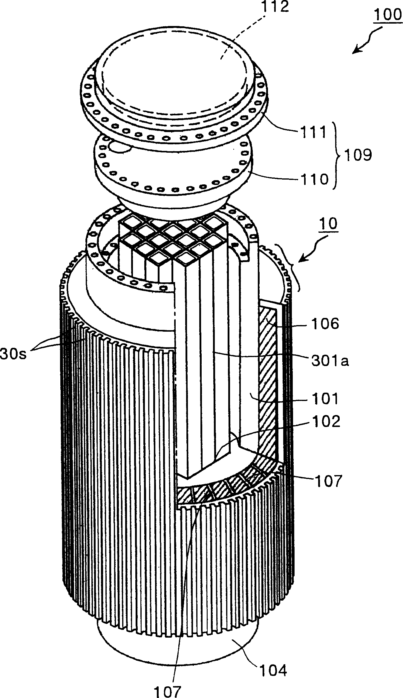
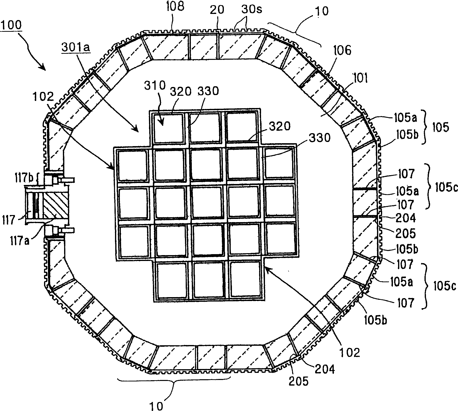
[0133] figure 1 It is a perspective view showing the shielding tank according to Embodiment 1 of the present invention. figure 2 yes figure 1 A radial cross-sectional view of the shielding tank shown. The shielding tank 100 is characterized by having an outer cylinder 10 composed of a plurality of belt-shaped members 105a, 105b, and grooves 30s in the axial direction of the cylinder body are formed on the plurality of belt-shaped members 105a, 105b. In addition, in figure 1 In, the outer cylinder 10 and the cylinder body 102 are briefly described, but the actual outer cylinder 10 and the cylinder body 102 are as follows figure 2 The shape and composition shown. Next, the configuration of the shielding tank 100 according to Embodiment 1 will be described.
[0134]In this shielding tank 100, the inner surface of the inner cavity 102 of the cylinder body 101 is machined in accordance with the outer peripheral shape of the hanging basket 301a. The machining of the inner...
Deformed example 1
[0211] Figure 28 It is an explanatory drawing showing the outer cylinder of the shielding can of the 1st modification of Embodiment 1. The outer cylinder 11 of this shielding tank has substantially the same structure as the outer cylinder 10 of the shielding tank in Embodiment 1, but the difference lies in that a plurality of The groove 31 s has an inclination angle θ with respect to the axial direction (arrow Z direction in the figure) of the barrel body 101 of the shielding tank. Since other configurations are the same as those in Embodiment 1, description thereof will be omitted, and the same reference numerals will be used.
[0212] Such as Figure 28 As shown, a plurality of grooves 31s having an inclination angle θ with respect to the axial direction of the cylinder body 101 of the shielding tank are formed on the heat dissipation surface side of the belt-shaped member 105a forming the outer cylinder 11 . The depth h and width l of the groove 31s are as described in ...
Deformed example 2
[0215] Figure 29 It is an explanatory drawing showing the outer cylinder of the shielding can of the 2nd modification of Embodiment 1. The outer cylinder 12 of this shielding tank has substantially the same structure as the outer cylinder 10 of the shielding tank of Embodiment 1, but the difference lies in that: a heat dissipation surface (surface above the paper surface in the figure) is provided with a The groove 32s facing the circumferential direction of the cartridge body 101 . Since other configurations are the same as those in Embodiment 1, description thereof will be omitted, and the same reference numerals will be used.
[0216] Such as Figure 29 As shown in (a), a plurality of grooves 32 s are formed on the heat dissipation surface side of the band-shaped member 105 a forming the outer cylinder 12 . The heat dissipation fins 32f are formed on the heat dissipation surface side of the band member 105a and the like by the grooves 32s. In addition, the depth h and ...
PUM
 Abstract
Description
Claims
Application Information
 - R&D
- Intellectual Property
- Life Sciences
- Materials
- Tech Scout
- Unparalleled Data Quality
- Higher Quality Content
- 60% Fewer Hallucinations
Browse by: Latest US Patents, China's latest patents, Technical Efficacy Thesaurus, Application Domain, Technology Topic, Popular Technical Reports.
© 2025 PatSnap. All rights reserved.Legal|Privacy policy|Modern Slavery Act Transparency Statement|Sitemap|About US| Contact US: help@patsnap.com


