Planar resonator for wireless power transfer

A resonator, series resonator technology, applied in resonators, inductors, transformers, etc., to achieve the effect of surface flexibility

Inactive Publication Date: 2005-08-31
KONINKLIJKE PHILIPS ELECTRONICS NV
View PDF1 Cites 25 Cited by
  • Summary
  • Abstract
  • Description
  • Claims
  • Application Information

AI Technical Summary

Problems solved by technology

Therefore, the prior art lacks a non-contact power transfer system that includes the capacitive coupling function of electric flux in addition to the inductive coupling of magnetic flux

Method used


Image

  • Planar resonator for wireless power transfer
  • Planar resonator for wireless power transfer
  • Planar resonator for wireless power transfer

Examples


Embodiment Construction

[0037] The following description is illustrative only and not limiting. Many different configurations are also within the spirit of the invention and scope of the appended claims.

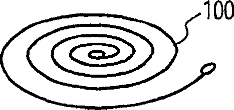
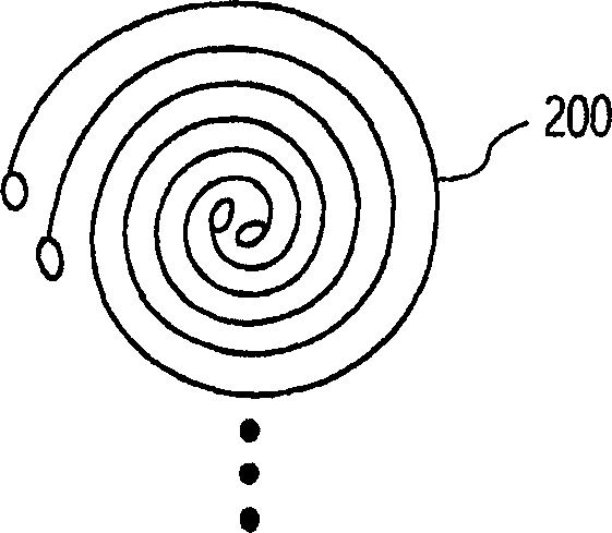
[0038] Figures 1A-1B A variation of a desperately integrated resonator according to an aspect of the invention is shown. Integrated resonators are obtained by storing electrical energy in a part of the structural (geometric) time-energy function, and magnetic energy in a part of the same function.

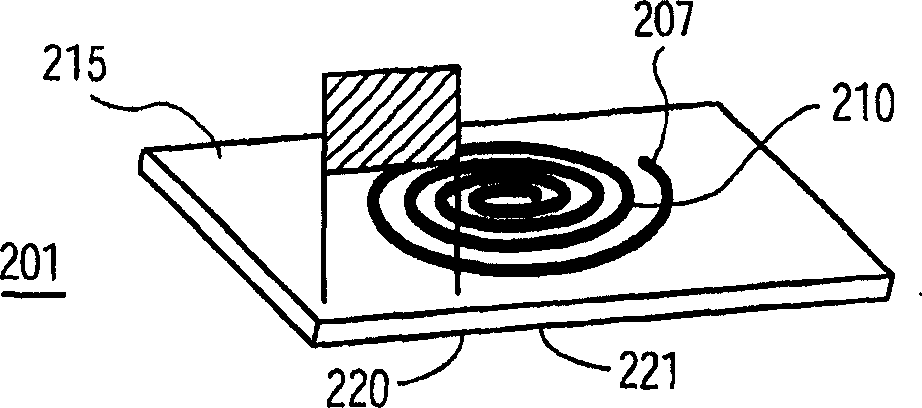
[0039] Figure 1A shows an example of a basic helix 100, while Figure 1B A bifilar helix 200 is shown. Of course, those of ordinary skill in the art will understand that the present invention is not limited to helical and bifilar helical, and any number of helical windings (multi-filar) may be used as desired. As shown in FIG. 2, the plane 200 has a helix 210 wound on the top surface of the energy transfer interface (IOET) 215, and another helix (not shown) wound on the bottom surface 220 of the e...


PUM


Abstract

A planar resonator and method of manufacture provides contactless power transfer using at least two electrically isolated axis aligned conductive across the transfer interface in a coupled inductor or transformer configuration. Signal or power transfer is then accomplished by coupling of magnetic flux. The coupling of electric flux is also accomplished across a same interface and driven with the same conductive spiral-wound conductors. An interface of energy transfer(IOET) has a first spiral-shaped conductor arranged on the top surface of said IOET; a second spiral-shaped conductor arranged on the bottom surface of said IOET, has a vertical axis aligned with the first spiral-shaped conductor. The IOET and the first and second spiral-shaped conductors have a predetermined self-resonant frequency. The planar power resonator stores electric energy in the IOET, and at predetermined frequencies, the arrangement of the first and second spiral-shaped conductors and the IOET permits transfers of magnetic flux and electrical energy between the first and second spirals across the IOET. The resonator facilitates contactless battery charging in devices such as cellphones and wearable electronics where the resonator can be woven into fabric or attached to a person's clothes.

Description

technical field [0001] The present invention relates to contactless power transfer systems. More specifically, the present invention designs planar resonators for wireless power transfer in contactless power transfer systems. Background technique [0002] Contactless power transfer is used in applications such as non-invasive pacemaker battery charging, hybrid vehicle battery charging. Inductive coupling is used exclusively in such applications, so that current is induced from the generating station to the load. In such systems, power transfer is achieved exclusively by means of coupled magnetic flux from the generating station and the load. [0003] For example, states such as California are already working on road systems that encourage trolley use. In such a system, an inductively coupled flat coil is embedded in the road, or a cable embedded in the road is energized, so that the induction coil of the vehicle receives an induced current from the road coil in order to a...

Claims


Application Information

Patent Timeline
Patent Type & Authority Applications(China)
IPC IPC(8): H01P7/00H01F17/00H01F38/14H02J7/02
CPCH02J7/025H01F17/0006H01F38/14H01P7/00H03H7/01H02J50/12
Inventor W·G·奥登达亚Y·李
Owner KONINKLIJKE PHILIPS ELECTRONICS NV
Why Eureka
Try Eureka