Wiper blade type hydraulic retarder for automobile
A scraper type, retarder technology, applied in the direction of hydraulic resistance brakes, brakes, vehicle parts, etc., can solve the problems of frequent water discharge, inconvenient operation, coil fire and burning, etc., to reduce internal volume and strong product stability. , cost saving effect
- Summary
- Abstract
- Description
- Claims
- Application Information
AI Technical Summary
Problems solved by technology
Method used
Image
Examples
specific Embodiment 1
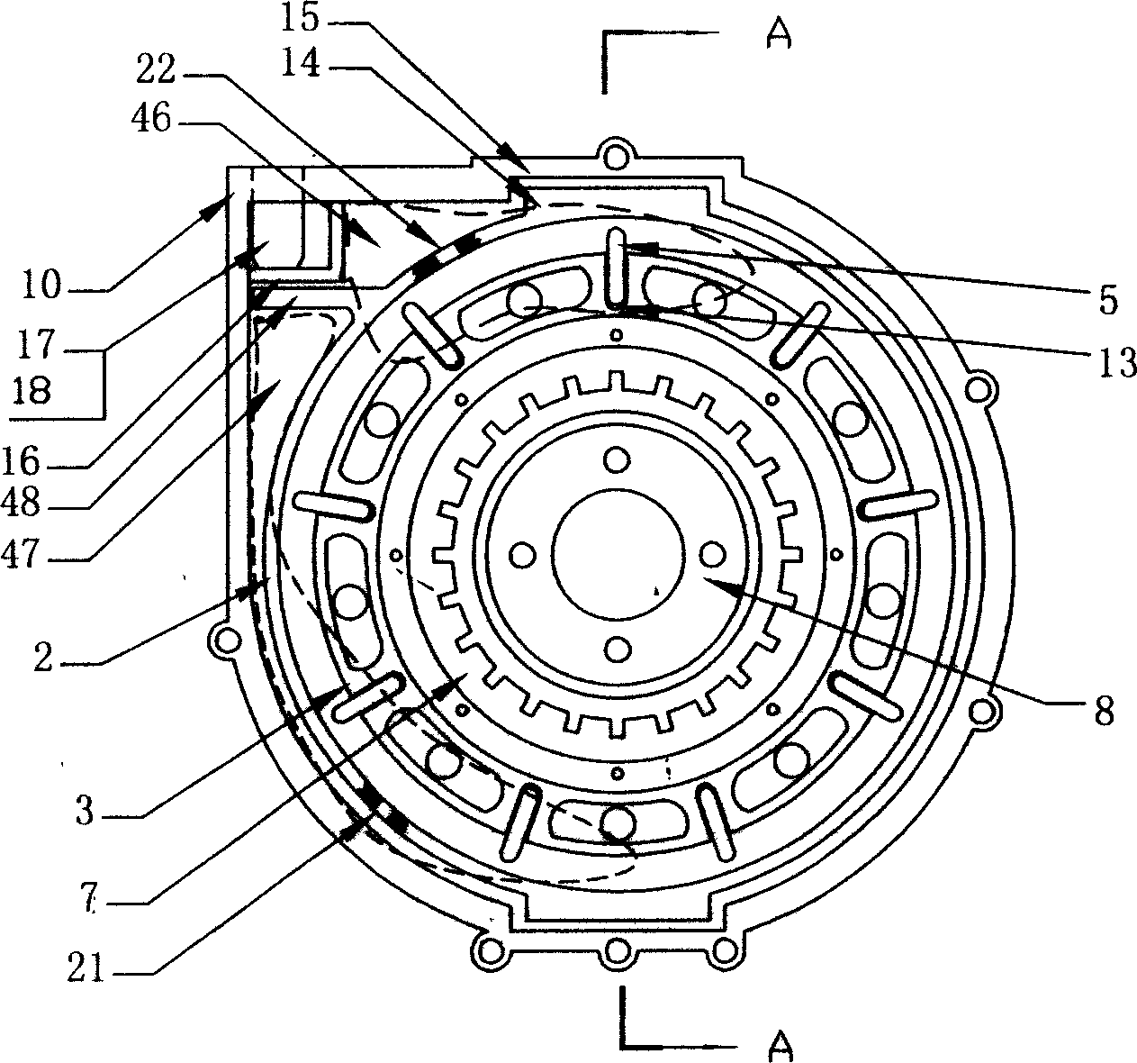
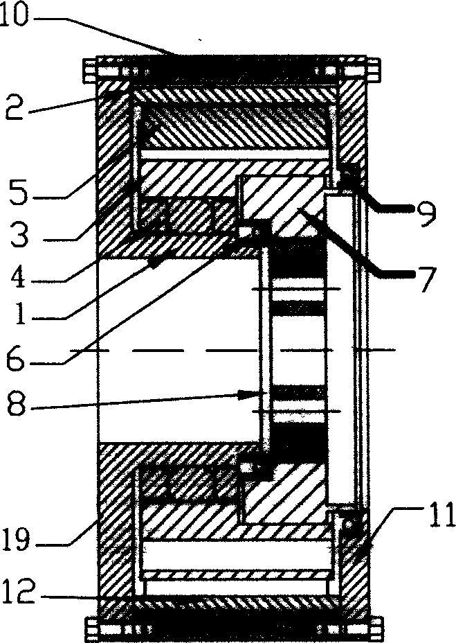
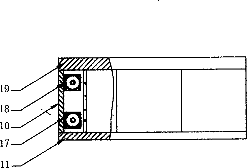
[0037] exist figure 1 , figure 2 , image 3 , Figure 5 Among them, the scraper type hydraulic retarder is composed of a housing, a rotor 3, a stator 2, an isolation device, and a pressure regulator. The housing is composed of a cylindrical shell 10, a front pressing plate 19 with a hole in the middle and a rear pressing plate 11 with a hole 26 in the middle. Both ends of the cylindrical housing 10 are connected and sealed to the front pressing plate 19 and the rear pressing plate 11 . The right side of the hole provided by the front pressing plate 19 is provided with a cylindrical inner shaft sleeve 1, and the front pressing plate 19 and the inner shaft sleeve 1 are integrally formed. The inner shaft sleeve 1 is located in the cavity of the housing 10 . The movable cylindrical stator 2 is coaxial with the inner shaft sleeve 1 and is located in the annular gap formed by the inner shaft sleeve 1 and the outer casing 10 . The side wall of the stator 2 is provided with an ...
specific Embodiment 2
[0047] like Figure 11 As shown, the feature of this embodiment is that the control device is a rotatable eccentric wheel 20 in the mounting housing that is in contact with the outer wall surface of the stator 2 . The rotation of the eccentric 20 drives the stator 2 to move. The front pressure plate 19 of the casing and the casing 10 are integrally formed, and the casing, the rotor 3 and the stator 2 can also be made of stainless steel. At this time, the pressure regulating control switch on the mounting seat 16 is replaced by a single relief valve, and the pressure regulating device 17 can also be removed. The rest are the same as in specific embodiment 1. The working principle is basically the same as that of the specific embodiment 1, the difference is that the movement control of the stator 2 is completed by the eccentric wheel 20 .
PUM
 Abstract
Description
Claims
Application Information
 - R&D
- Intellectual Property
- Life Sciences
- Materials
- Tech Scout
- Unparalleled Data Quality
- Higher Quality Content
- 60% Fewer Hallucinations
Browse by: Latest US Patents, China's latest patents, Technical Efficacy Thesaurus, Application Domain, Technology Topic, Popular Technical Reports.
© 2025 PatSnap. All rights reserved.Legal|Privacy policy|Modern Slavery Act Transparency Statement|Sitemap|About US| Contact US: help@patsnap.com


