Test tube holder

A technology for cages and test tubes, applied in test tube holders/clamps, instruments, paving details, etc., can solve problems such as troublesome maintenance, poor assembly processability, and high manufacturing costs, and achieve lower prices, lower damage possibilities, and excellent durability Effect

Inactive Publication Date: 2005-09-28
IDS CO LTD
View PDF1 Cites 15 Cited by
  • Summary
  • Abstract
  • Description
  • Claims
  • Application Information

AI Technical Summary

Problems solved by technology

[0005] As mentioned above, the existing test tube holder has a complicated structure, and the elastic force of the leaf spring is supplemented by an O-ring
Therefore, assembly workability is poor, manufacturing cost is high, and maintenance is troublesome when the O-ring is damaged

Method used


Image

  • Test tube holder
  • Test tube holder
  • Test tube holder

Examples


Embodiment Construction

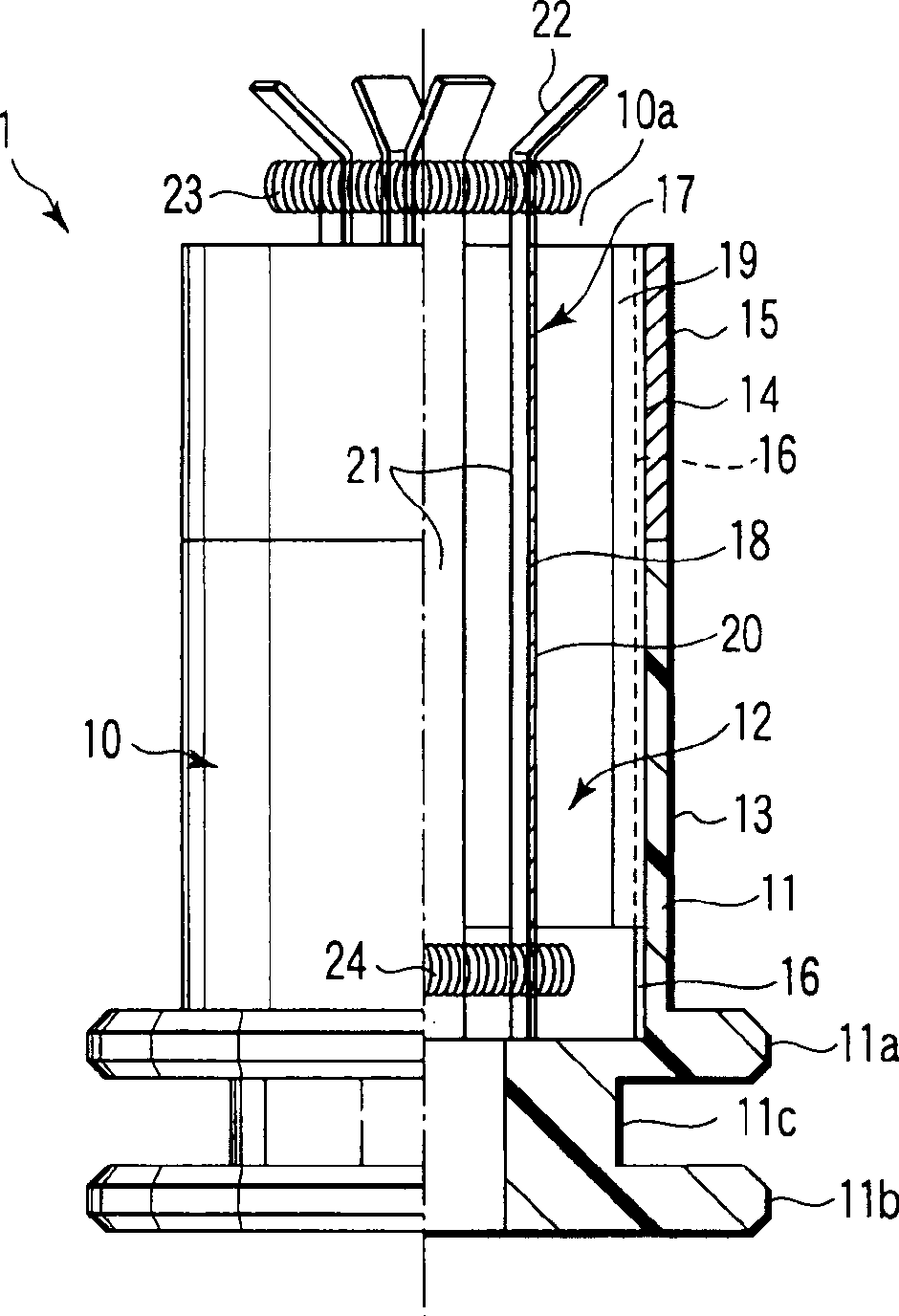
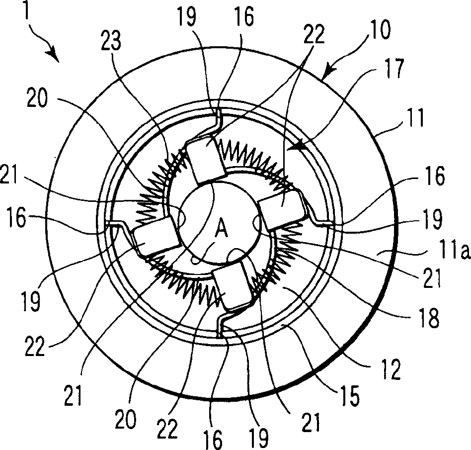
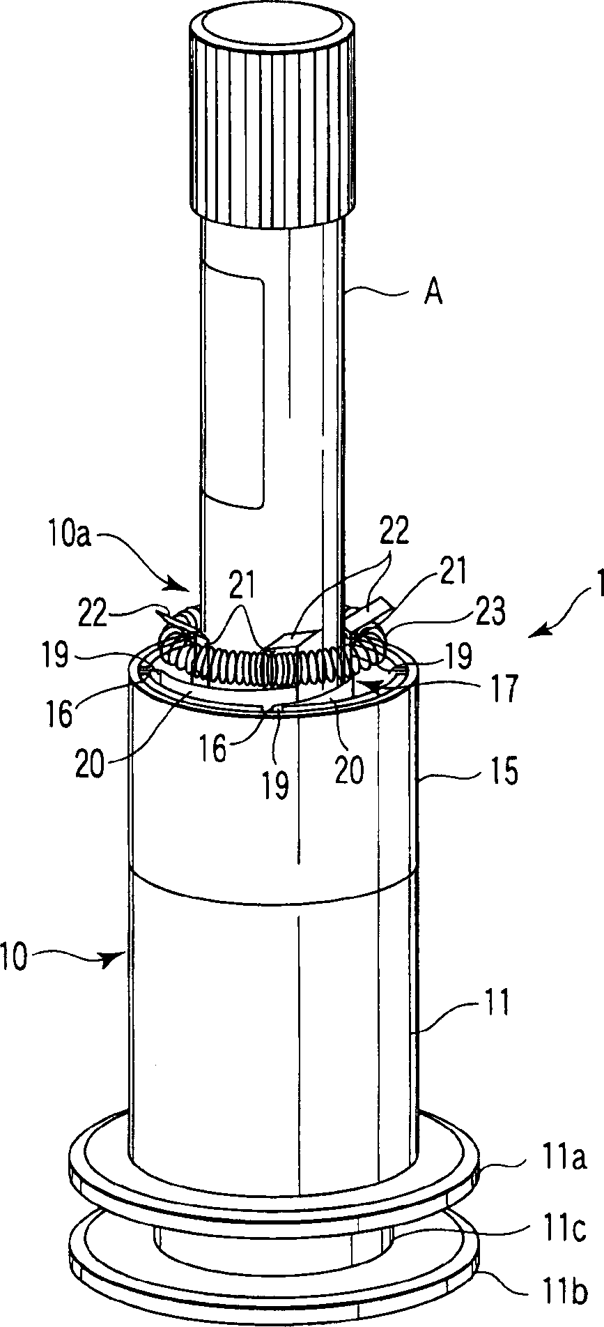
[0016] Below to Figure 1 ~ Figure 3 The test tube holder 1 of the embodiment of the present invention will be described in detail.

[0017] The test tube holder 1 of the embodiment of the present invention has a holder main body 10 and a test tube fixing adapter 17 . The holder main body 10 is formed of a synthetic resin material. In the holder main body 10, the joint part that can be connected with the transfer system guide rail (not shown), that is, the vertical two-layer flange parts 11a and 11b in the embodiment, is formed on the outer peripheral surface of the proximal part of the cylindrical base 11 , and an annular groove 11c is provided between the flange portions.

[0018] At the axial center portion of the cylindrical base 11, a cylindrical hollow portion 12 for inserting a test tube is provided at a depth from the tip end portion to a position corresponding to the flange portion 11a located on the upper stage. The outer periphery of the middle region of the cyli...


PUM


Abstract

A test tube holder has a holder main body, which has a cylindrical hollow portion for containing a test tube, and a test tube attachment adapter arranged in the cylindrical hollow portion. The test tube attachment adapter for holding a test tube is configured by plural leaf springs and coil springs and. Each of the leaf springs has a fixed portion, an elastic deformable portion and a test tube holding piece. The fixed portion is fixed to the inner circumference of the cylindrical hollow portion along the axial direction thereof. The elastic deformable portion extends along the circumferential direction from the fixed portion toward the center axis while leaning in the centripetal direction. The test tube holding piece is formed integrally with the elastic deformable portion. The coil springs bundle a top and a bottom end portions of the plural test tube holding pieces.

Description

technical field [0001] The present invention relates to a test tube holder which is used for transferring test tubes in order to receive or provide a sample contained in the test tube, such as blood. Background technique [0002] A test tube containing a sample such as blood is made of transparent glass, and a cap made of rubber or artificial resin material is attached to the top opening of the test tube. For the preparatory reception or preparatory provision of the samples contained in the test tubes, the test tubes are transferred to the respective processing device while being held upright by the test tube holders guided along the transfer path. [0003] Therefore, the test tube holder constructed in this way serves to hold the test tubes upright in a stable manner and to transfer them. The test tube holder has a base body forming the main body of the holder. The base body has a connection part that engages on the outer peripheral surface of its proximal portion with th...

Claims


Application Information

Patent Timeline
Patent Type & Authority Applications(China)
IPC IPC(8): G01N35/04B01L9/00B01L9/06G01N1/00
CPCB01L2200/023B01L9/06E01C11/225E01C2201/202
Inventor 伊藤照明
Owner IDS CO LTD
Why Eureka
Try Eureka