Manufacturing system for microstructure

A manufacturing system and microstructure technology, applied in the direction of microstructure technology, microstructure devices, manufacturing microstructure devices, etc., can solve the problems of low moving speed, small stroke, etc., and achieve high precision and stroke characteristics, high vacuum applicability, Effect of large stroke characteristics

Inactive Publication Date: 2005-10-12
MITSUBISHI HEAVY IND MACHINE TOOL CO LTD
View PDF1 Cites 4 Cited by
  • Summary
  • Abstract
  • Description
  • Claims
  • Application Information

AI Technical Summary

Problems solved by technology

[0014] This method can only achieve small strokes and low moving speeds

Method used


Image

  • Manufacturing system for microstructure
  • Manufacturing system for microstructure
  • Manufacturing system for microstructure

Examples


Embodiment Construction

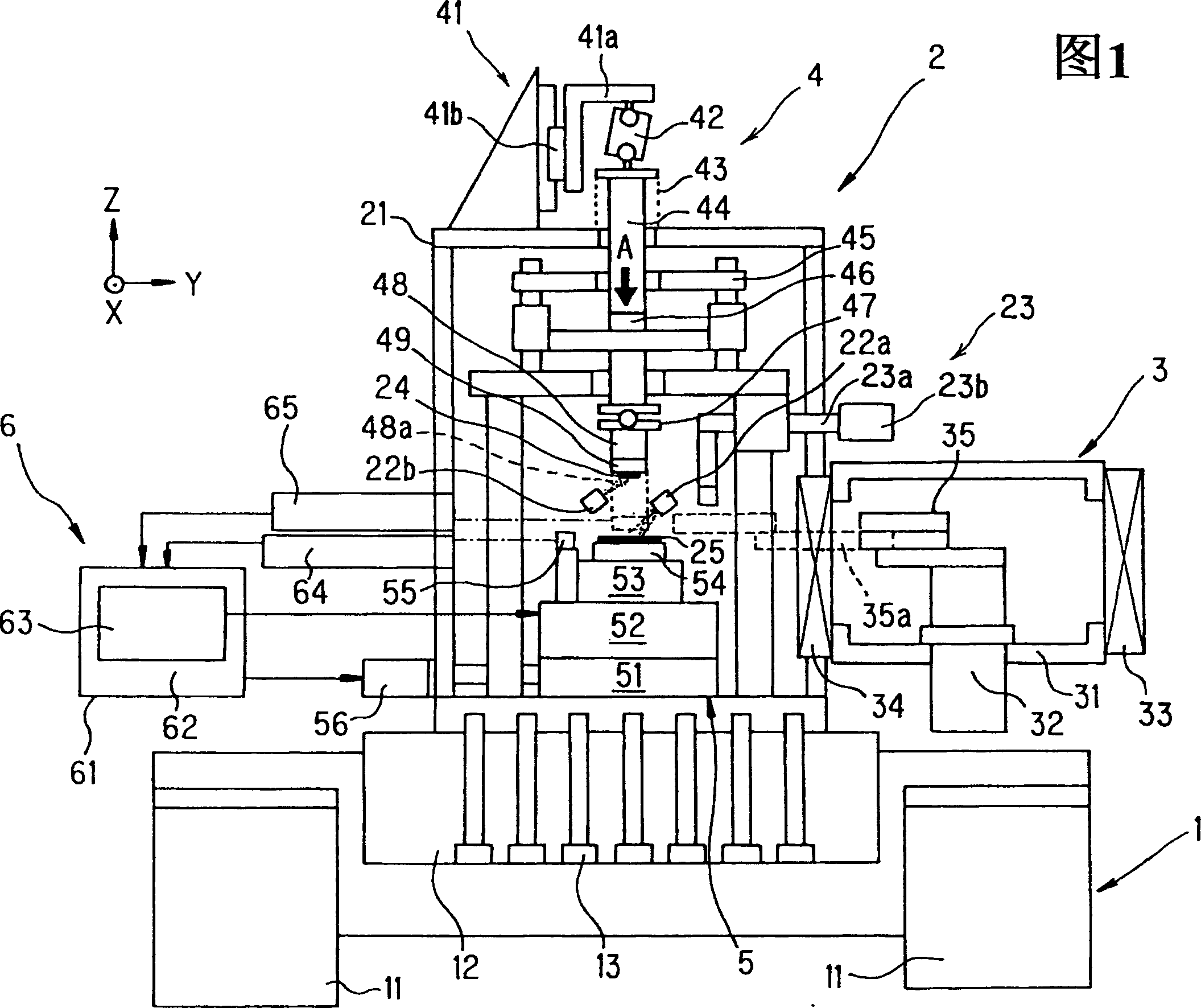
[0053] The microstructure manufacturing system according to the present invention is configured to combine and laminate a plurality of thin film elements and the like and thereby manufacture microstructures, by element positioning a plurality of thin film elements having arbitrary two-dimensional patterns or three-dimensional patterns, including a plurality of arbitrary two-dimensional A substrate (crimped member) of a pattern or a three-dimensional pattern or the like is set oppositely with respect to a crimping target member, then crimping and separation are performed, and then these steps are repeated.

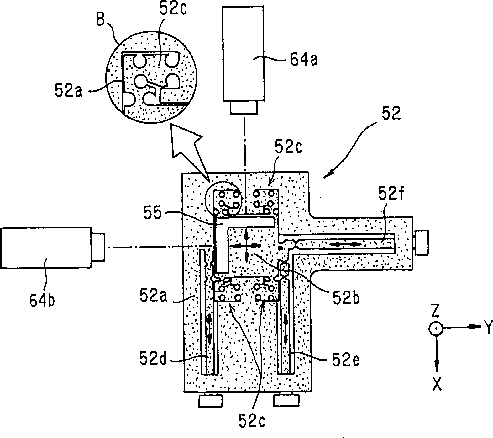
[0054] In the microstructure manufacturing system according to the present invention, a high degree of positioning accuracy is obtained by using a table device, wherein a large-stroke coarse motion table (first table) with a preset positioning accuracy is provided with a Small-stroke micro-motion worktable (second workbench) with higher positioning accuracy of the worktable....


PUM


Abstract

A manufacturing system for a microstructure includes a rough motion stage having predetermined positioning accuracy and a large stroke length, a fine motion stage disposed on the rough motion stage and having higher positioning accuracy than the rough motion stage and a small stroke length, and the like collectively as a stage device disposed in a vacuum container, laser length measuring machines for measuring a distance to a mirror disposed on the fine motion stage, a stage control device for driving the fine motion stage by a result of measurement by the laser length measuring machines, and the like collectively as a stage control unit, and a pressing rod 44 for holding a pressure-contacting target member disposed opposite to a pressure-contacted member held by the stage device and pressure-contacting and separating the members, a pressure-contacting drive mechanism for applying a pressure-contacting force to the pressing rod 44, and the like collectively as a pressure-contacting mechanism unit.

Description

[0001] The entire contents of Japanese Patent Application No. 2004-111769 filed on Apr. 6, 2004, including specification, claims, drawings and abstract, are hereby incorporated by reference in their entirety. technical field [0002] The invention relates to a system for the manufacture of microstructures formed from laminated film elements. Background technique [0003] With the development of finishing technology in recent years, many methods of manufacturing microstructures in three-dimensional form have been developed. Among these methods, a lamination molding method of transferring and laminating onto a substrate using a room temperature bonding method is attracting attention. This method is to use semiconductor processing technology to form each cross-sectional shape along the lamination direction of the microstructure as a bulk thin film element on the substrate, separate each cross-sectional shape, that is, each thin film element from the substrate, and use room temp...

Claims


Application Information

Patent Timeline
Patent Type & Authority Applications(China)
IPC IPC(8): B81C3/00B29C65/00B81C99/00
CPCB29C65/006B29C67/0096B29C65/002B29C66/022Y10T74/20354B29C66/73161B29K2995/0072B29C66/9672B29C65/7817B29C66/0222B29C66/028B29C64/35B29C66/7352
Inventor 津野武志后藤崇之田原谕木之内雅人浅野伸长谷川修山田高幸高桥睦也
Owner MITSUBISHI HEAVY IND MACHINE TOOL CO LTD
Why Eureka
Try Eureka