Vehicle steering telescopic shaft
A technology of telescopic shaft and steering shaft, which is applied to the steering column, steering control installed on the vehicle, steering control, etc., which can solve the difficulty of miniaturization of the telescopic shaft for vehicle steering, difficulty in crushing/crushing stroke, and processing cost Elevation and other issues
- Summary
- Abstract
- Description
- Claims
- Application Information
AI Technical Summary
Problems solved by technology
Method used
Image
Examples
no. 1 Embodiment
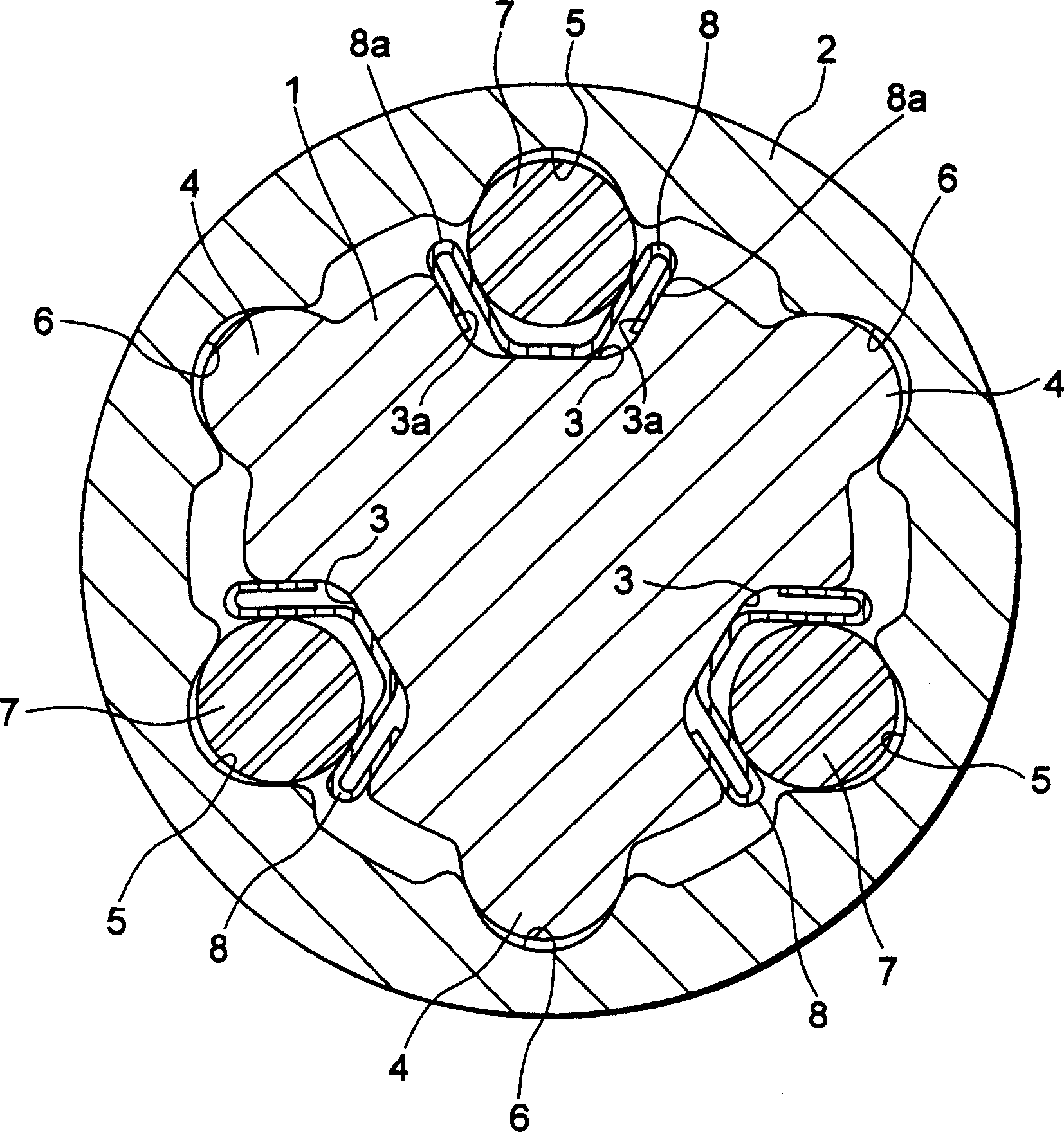
[0039] figure 2 It is an axial central sectional view of a vehicle steering telescopic shaft according to a first embodiment of the present invention, image 3 is along figure 2The cross-sectional view of the X-X line, Figure 4 It is a graph showing the relationship between the stroke and the sliding load of the vehicle steering telescopic shaft of the first embodiment.
[0040] Such as figure 2 , image 3 As shown, the telescopic shaft for vehicle steering (hereinafter referred to as the telescopic shaft) is composed of two male shafts 1 and 2 that are non-rotatable and slidably engaged with each other.
[0041] In the first embodiment, on the outer peripheral surface of the male shaft 1 , three axial ridges 4 extending in the axial direction and each having a substantially arc-shaped cross-section are formed at intervals of 120° along the circumferential direction. Correspondingly, on the inner peripheral surface of the female shaft 2 at the positions opposite to the t...
no. 2 Embodiment
[0066] Figure 5 It is an axial central cross-sectional view of a vehicle steering telescopic shaft according to a second embodiment of the present invention. Image 6 is along Figure 5 Cross-sectional view of the X-X line. The same configurations as those in the first embodiment are given the same reference numerals and their descriptions are omitted.
[0067] The second embodiment differs from the first embodiment in that a solid lubricant film 11 is formed on the outer peripheral surface of the male shaft 1 . In this way, by forming the solid lubricating film 11 on the outer peripheral surface of the male shaft 1, the contact resistance between the axial ridge 4 and the axial groove 6 of the torque transmission part can be reduced, and compared with the case of the first embodiment, it can The total sliding load (that is, the sliding load that occurs during normal use in the configuration of the present invention in which both rolling and sliding act) is lowered.
[00...
no. 3 Embodiment
[0073] Figure 7 It is an axial central sectional view showing a vehicle steering telescopic shaft according to a third embodiment of the present invention. Figure 8 is along Figure 7 Cross-sectional view of the X-X line. The same structures as those in the second embodiment are given the same symbols and their descriptions are omitted.
[0074] The difference between the third embodiment and the second embodiment is that the male shaft 1 is formed into a hollow structure (hollow part 13), so as to realize the overall weight reduction of the vehicle steering telescopic shaft, and by forming the male shaft 1 as The stopper plate 12 is inserted into the hollow portion 13 of the male shaft 1 for riveting due to its hollow structure. The other configurations, functions, and effects are the same as those of the second embodiment, and description thereof will be omitted.
[0075] Furthermore, in the third embodiment, although the solid lubricant film 11 is formed on the entire...
PUM
 Abstract
Description
Claims
Application Information
 - R&D
- Intellectual Property
- Life Sciences
- Materials
- Tech Scout
- Unparalleled Data Quality
- Higher Quality Content
- 60% Fewer Hallucinations
Browse by: Latest US Patents, China's latest patents, Technical Efficacy Thesaurus, Application Domain, Technology Topic, Popular Technical Reports.
© 2025 PatSnap. All rights reserved.Legal|Privacy policy|Modern Slavery Act Transparency Statement|Sitemap|About US| Contact US: help@patsnap.com


