Gas heating method and gas heating device

A gas heating and equipment technology, applied in lighting and heating equipment, air heaters, fluid heaters, etc., can solve the problems of large power loss, ineffective heating of flowing gas, and easy to be corroded by gas.

Inactive Publication Date: 2005-10-19
SUMITOMO ELECTRIC IND LTD
View PDF2 Cites 19 Cited by
  • Summary
  • Abstract
  • Description
  • Claims
  • Application Information

AI Technical Summary

Problems solved by technology

[0014] However, the above-mentioned conventional exhaust gas treatment equipment has such a disadvantage that the heater for heating the exhaust gas either indirectly heats the gas without contacting the gas, or even if the heater contacts the gas, since a general resistance heating element is used as the heater, the They are easily corroded by gases; and, in addition, the heating time is prolonged due to the ineffective heating of the flowing gas, thereby causing considerable power loss
Another problem is that in order to heat a specified amount of gas, the heating chamber must be made very large, which means making the equipment too large

Method used


Image

  • Gas heating method and gas heating device
  • Gas heating method and gas heating device
  • Gas heating method and gas heating device

Examples


Embodiment

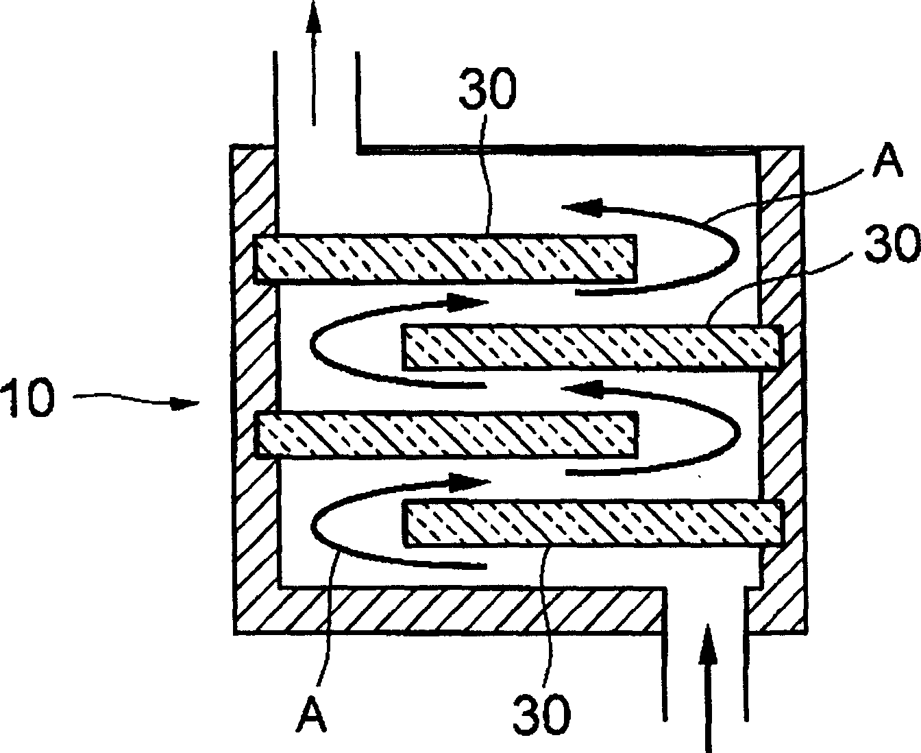
[0050] The gas heating device according to the invention is used in a device for treating harmful exhaust gases, which is used in sterilization and disinfection processes in hospitals. In particular, as Figure 7 As shown, there are four heater assemblies 35, four ceramic heaters are combined in each heater assembly, and the heater assemblies are arranged in the housing 23 in the form of staggered ledges, so that the housing 23 A zigzag gas flow path is formed in the center, thereby serving as the heating device 22 for heating the harmful exhaust gas supplied through the harmful gas introduction port 22a.

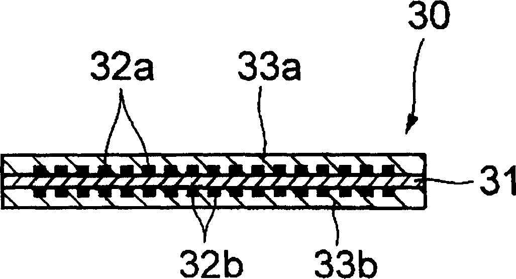
[0051] Specifically, the heating device 22 is equipped with a shell 23 made of SUS steel, and the interior of the shell is 430mm x 430mm x 480mm high; internally so as to form staggered ledges spaced 90mm apart from each other. Here, the structure of each heater assembly 35 is as follows Figure 5 One structure shown: four ceramic heaters 30 assembled into a flat planar ...


PUM


Abstract

Made available are a gas-heating method and a small-scale, energy-saving gas-heating device that, utilizing heaters that enable high-speed gas heat-up without being corroded by the gas, make possible the direct, efficient heating of gases. A plurality of platelike ceramic heaters 30 , or heater units in which a number of ceramic heaters are combined, is arranged in a staggered-ledge formation within a flow path or heating chamber for gases to create a zigzag gas flow-path A; gas supplied to the gas flow-path A is heated directly by the ceramic heaters 30 or heater units. This gas-heating device 10 can be utilized, in apparatuses that process NOx:containing exhaust gases or noxious / poisonous exhaust gases, for heating the exhaust gases and their diluent gases.

Description

technical field [0001] The present invention relates to methods of heating gases and gas heating equipment for use in various chemical reactors—for example, gas heating equipment for devices that contain NO and are exhausted from semiconductor devices and liquid crystal manufacturing processes. X or NH 3 Devices for the treatment of exhaust gases, devices for the treatment of harmful or toxic exhaust gases from sterilization and disinfection processes in hospitals, and other such devices. Background technique [0002] The semiconductor device manufacturing process includes a wafer processing stage in which semiconductor wafers are processed to produce integrated circuits. Various processes such as thin film deposition operations, oxidation operations, doping operations, and etching operations are performed in the wafer processing stage to form, for example, dielectric films, electrode wirings, and semiconductor films on the wafer front side. [0003] In carrying out variou...

Claims


Application Information

Patent Timeline
Patent Type & Authority Applications(China)
IPC IPC(8): F23G7/06B01D53/56B01D53/58B01D53/68B01D53/70B01D53/72F24H3/04F27B9/36F27D11/02F27D17/00H01L21/00
CPCH01L21/67109F24H3/0405F23G7/06F24H3/04
Inventor 桥仓学仲田博彦
Owner SUMITOMO ELECTRIC IND LTD
Why Eureka
Try Eureka