Process for producing high-purity terephthalic acid
A terephthalic acid, high-purity technology, applied in the field of preparing high-purity terephthalic acid, can solve the problems of reduction catalyst poisoning, activity reduction and the like
- Summary
- Abstract
- Description
- Claims
- Application Information
AI Technical Summary
Problems solved by technology
Method used
Image
Examples
Embodiment 1
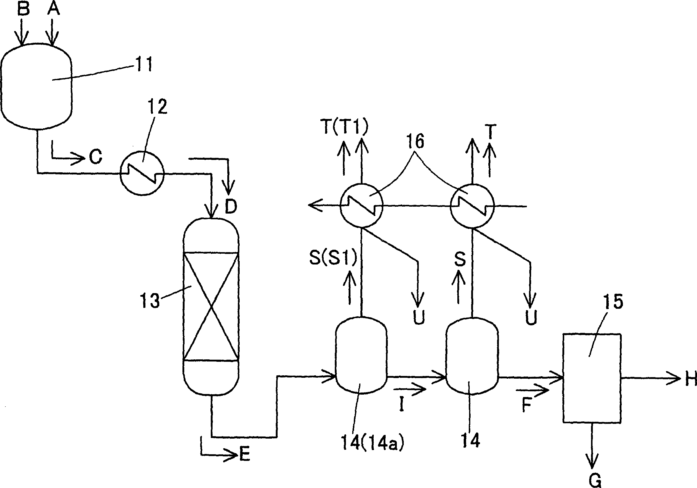
[0030] This example uses figure 1 The process shown is complete. Specifically, in the mixing tank 11, crude terephthalic acid containing 3,000 ppm of 4CBA and water were charged at 18 tons / hour to prepare a slurry C of 30% by weight of crude terephthalic acid. Pressurize the slurry C to a pressure of 8.9MPa, raise the temperature to 285°C through a multi-tubular heat exchanger 12 to dissolve terephthalic acid, and then inject the aqueous solution D of terephthalic acid into the hydrogenation reactor 13 middle. The hydrogenation reactor 13 had a column diameter of 1,260 mm and a height of 10 m, and 0.5% by weight of palladium attached to activated carbon was used as a reduction catalyst, and the amount of the catalyst charged was 6 tons. In this hydrogenation reactor 13, hydrogen gas was simultaneously injected to reduce the aforementioned aqueous solution D of terephthalic acid, and the resulting reduction treatment liquid E was crystallized in the subsequent crystallization...
Embodiment 2
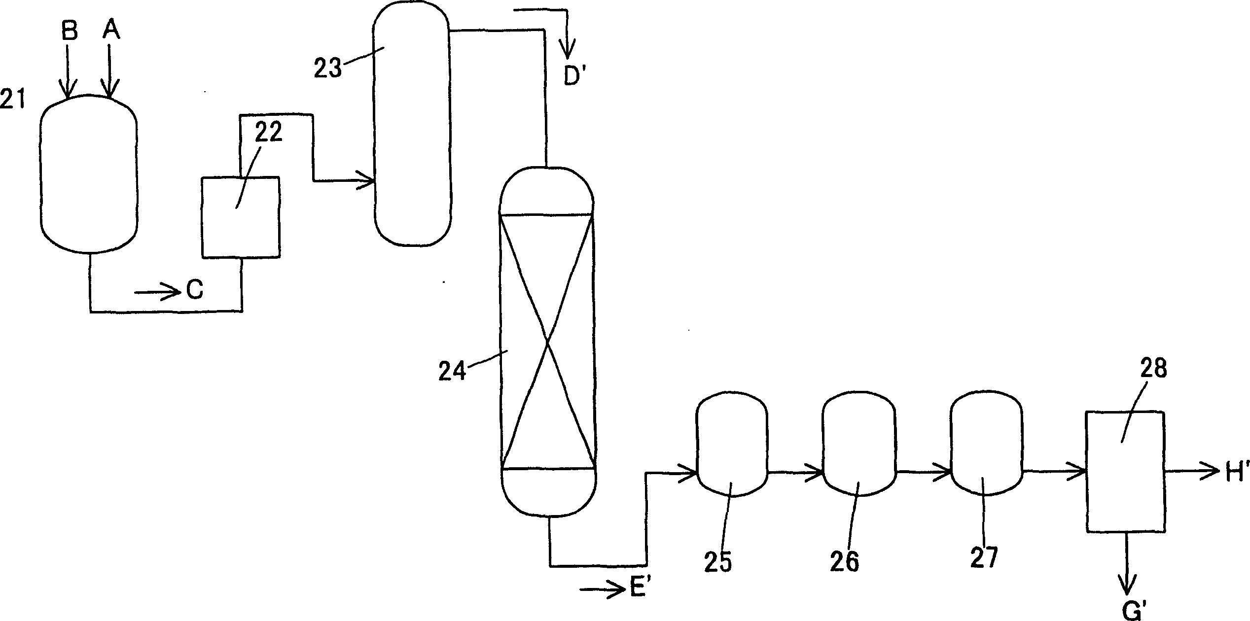
[0035] use figure 2 The process shown performs a hydrogenation reaction. Specifically, the crude terephthalic acid A containing 3,000 ppm of 4CBA and water B were charged at 1.2 kg / hr in the metering tank 21 to prepare a slurry C of 20% by weight of the crude terephthalic acid. Pressurize the slurry C to a pressure of 7.9 MPa, raise the temperature to 280°C through the preheater 22, dissolve terephthalic acid in the dissolution tower 23, and then inject the aqueous solution D' of terephthalic acid into the hydrogenation reaction device 24. The hydrogenation reactor 24 had a column diameter of 15 mm and a height of 1,450 mm, and 0.5% by weight of palladium attached to activated carbon was used as a reduction catalyst, and the catalyst filling amount was 120 g. In this hydrogenation reactor 24, hydrogen gas is simultaneously injected to reduce the aforementioned aqueous solution of terephthalic acid. The obtained reduction treatment solution E' is temporarily stored in the r...
Embodiment 3
[0039] Operated under the same conditions as in the aforementioned Example 2, except that hydrogen / 4CBA was 3 (molar ratio), the ratio was the amount of hydrogen injected into the hydrogenation reactor 24 to the amount of 4CBA in the solution injected into the hydrogenation reactor 24 ratio.
[0040] Through this operation, the amount of carbon monoxide formed in the hydrogenation reactor was calculated as a ratio of carbon monoxide / 4CBA to 0.09 (molar ratio) relative to the amount of 4CBA in the solution injected into the hydrogenation reactor.
PUM
 Abstract
Description
Claims
Application Information
 - R&D
- Intellectual Property
- Life Sciences
- Materials
- Tech Scout
- Unparalleled Data Quality
- Higher Quality Content
- 60% Fewer Hallucinations
Browse by: Latest US Patents, China's latest patents, Technical Efficacy Thesaurus, Application Domain, Technology Topic, Popular Technical Reports.
© 2025 PatSnap. All rights reserved.Legal|Privacy policy|Modern Slavery Act Transparency Statement|Sitemap|About US| Contact US: help@patsnap.com


