Computer controlled filming device

A coating device and computer technology, applied in sputtering coating, vacuum evaporation coating, ion implantation coating, etc., can solve problems affecting stability, repeatability and monitoring accuracy, and artificial random factors, etc., to eliminate Stability and repeatability issues, easy portability, intuitive and friendly interface effects

Inactive Publication Date: 2005-11-16
SHANGHAI INST OF OPTICS & FINE MECHANICS CHINESE ACAD OF SCI
View PDF1 Cites 10 Cited by
  • Summary
  • Abstract
  • Description
  • Claims
  • Application Information

AI Technical Summary

Problems solved by technology

The system is monitored manually. Due to the large random factors, the stability, repeatability and monitoring accuracy are affected, and the optical film thickness monitor can only monitor the regular film system; in addition, some equipment

Method used


Image

  • Computer controlled filming device
  • Computer controlled filming device
  • Computer controlled filming device

Examples


Embodiment Construction

[0021] The present invention will be further described below in conjunction with the embodiments and accompanying drawings.

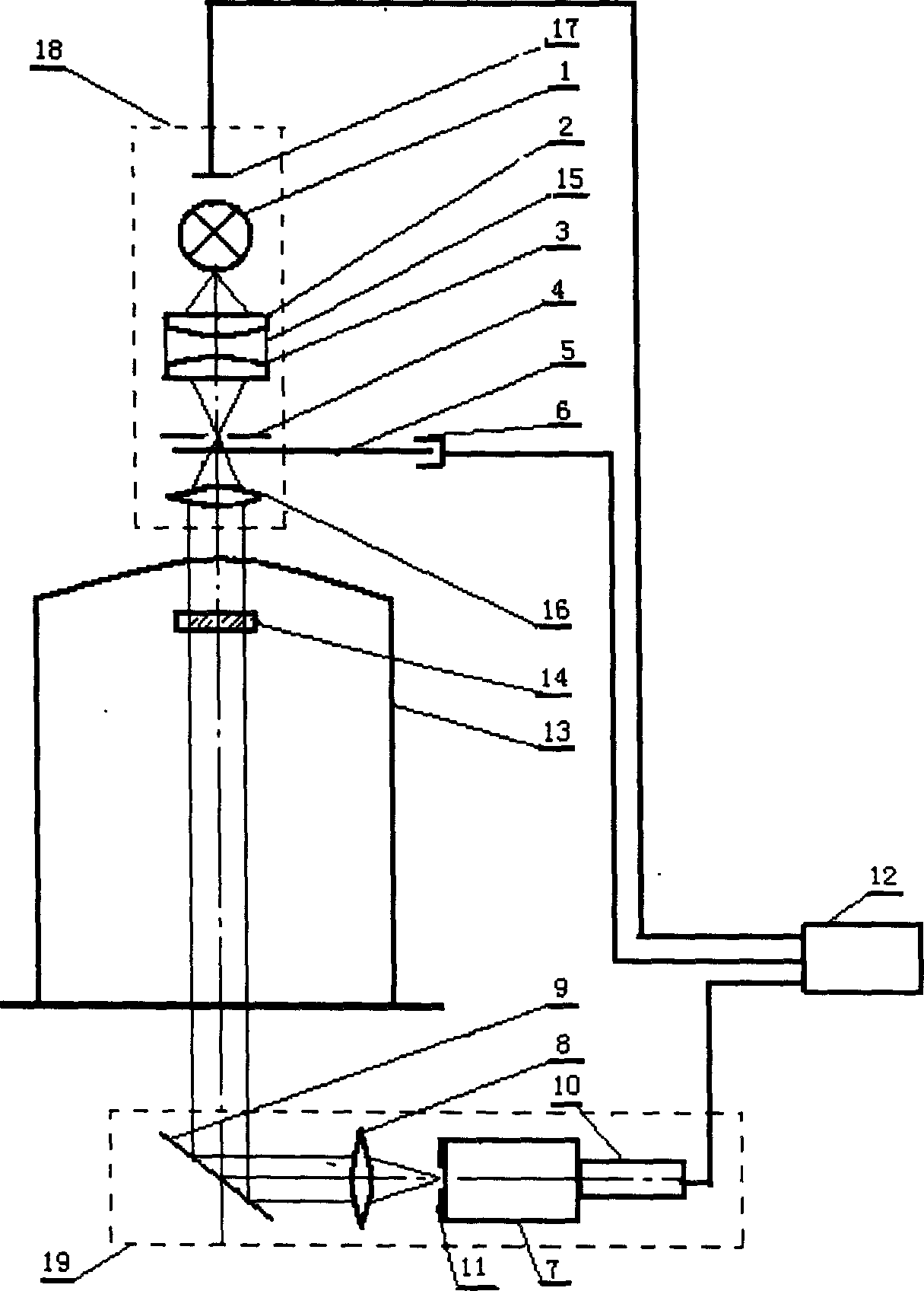
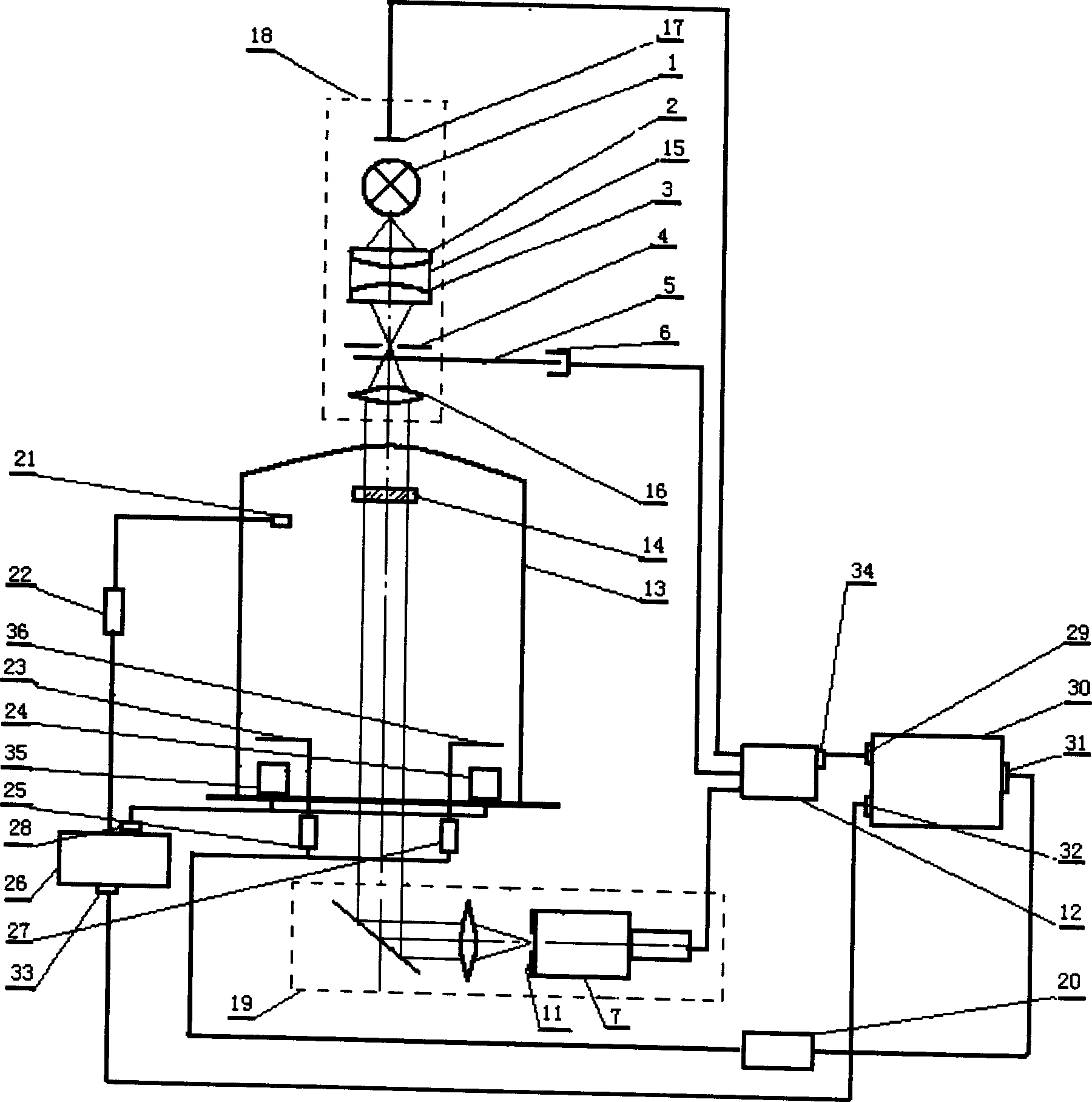
[0022] see first figure 2 , figure 2 It is a schematic structural view of the computer-controlled coating device of the present invention. As can be seen from the figure, the computer-controlled coating device of the present invention includes an optical film thickness monitoring system composed of a light source emitting system 18, a monitoring panel 14, a signal receiving system 19 and a lock-in amplifier 12. , it is characterized in that there are also: computer 30 with control program, crystal controller 26, baffle switch control circuit 20; the crystal oscillator head 21 of the crystal controller 26 is passed through the impedance matching device 22 and the crystal controller through the shielded wire 26 is connected; the evaporation source control voltage output end 28 of described crystal controller 26 is connected with the first evaporation s...


PUM


Abstract

A computer controlled plating apparatus is composed of an optical film thickness monitor system consisting of light source and emitting system, monitor chip, signal receiver system and phase-locked amplifier, the computer with control program consisting of parameter setting-up module and data processing module, crystal controller, and barrier switch controller.

Description

technical field [0001] The invention relates to film coating, in particular to a computer-controlled film coating device capable of monitoring regular film systems and irregular film systems. Background technique [0002] In the preparation of thin films, in addition to selecting appropriate materials and preparation processes, the thickness must also be precisely controlled. Thickness, as one of the most important optical film parameters, decisively affects the mechanical properties, electrical properties and optical properties of films; on the other hand, almost all film properties are related to thickness. Therefore, accurately controlling the thickness of the film becomes the key to the preparation of optical films. figure 1 The optical path diagram of the optical film thickness monitoring system (application number: 200510024987.1, application date: April 28, 2005) invented by the inventor is provided. The optical film thickness monitoring system is monitored by the li...

Claims


Application Information

Patent Timeline
IPC IPC(8): C23C14/54
Inventor 朱美萍易葵郭世海贺洪波邵建达范瑞瑛范正修齐红基
Owner SHANGHAI INST OF OPTICS & FINE MECHANICS CHINESE ACAD OF SCI
Why Eureka
Try Eureka