Supporting node

A technology of joints and ball joints, applied in the field of joints, can solve problems such as difficulty in ensuring installation accuracy, impossibility of optimization, unclear internal force of joints, etc., to achieve the effect of ensuring machining accuracy and quality, facilitating factory mass production, and easily guaranteeing machining quality

Inactive Publication Date: 2005-11-30
徐国彬 +1
View PDF0 Cites 12 Cited by
  • Summary
  • Abstract
  • Description
  • Claims
  • Application Information

AI Technical Summary

Problems solved by technology

These tasks must be produced and constructed on the grid or truss construction site, including blanking, cutting, assembly, welding, etc., so the on-site workload is large and the efficiency is low, which has caused an increase in construction costs to a certain extent; , because it is difficult to process arc-shaped joints, open slits, and weld rods or pipes and ribs on the spherical surface, it is difficult to guarantee the construction accuracy and construction quality during on-site construction, and the integrity is poor. Therefore, most truss structures or nets Most of the frame structure accidents occur at the node position; and, because the nodes and supporting devices are installed on site, the installation accuracy is difficult to guarantee, and because the node structure is complex and the force is not clear, it is also difficult to carry out the structure design. Accurate force analysis can only be estimated based on empirical values, and the internal force of nodes is not clear and cannot be optimized
[0005] In addition, due to the rigid connection between this kind of node and the column, when earthquakes or other operating or wind vibrations occur, the node will generate displacement or moment relative to the column. The risk of structural failure caused by cracking itself or disconnection of the joints from the fixed points of the piers

Method used


Image

  • Supporting node
  • Supporting node
  • Supporting node

Examples


Embodiment 1

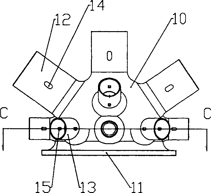
[0033] Figure 2 to Figure 7 A structural schematic diagram of a support node of the present invention is shown. It consists of a hemispherical body 10, a mounting base 11 with a flat bottom, and circular tubes 12, 13 on the hemispherical body 10.

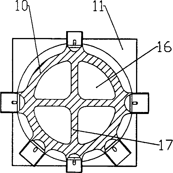
[0034] Depend on Figure 6 to Figure 7 It can be seen that the hemisphere 10 and the mounting support 11 are integrated, that is, the periphery of the bottom of the hemisphere protrudes outwards to form a square mounting support for easy installation on the support column. According to installation requirements, through holes can be provided on the outwardly protruding edge of the mounting support 11 so as to be installed by means of bolt fixing.

[0035] Such as Figure 6 , Figure 7 As shown, the round pipes 12, 13 and the hemisphere 10 connected to the rods or pipes in the truss or grid structure also adopt an integral structure, so that the supporting nodes form a whole, which can be produced by casting, and the product can...

Embodiment 2

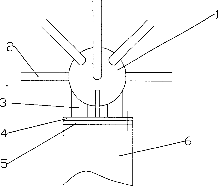
[0044] Such as Figure 8 As shown, the node part of the supporting node in this embodiment is composed of a hemisphere 10 and a round tube 12 on the hemisphere 10, and its structure is the same as that in Embodiment 1, and will not be described again in this embodiment. The difference from Embodiment 1 is that the mounting support part is a combined displacement support, including a box body 60 that can be fixed on the support column, and a guide rail 40 is installed in the box body 60 to slide on the bottom of the box body 60. The base 30 of the base 30 has an arc-shaped groove on the upper surface of the base 30, and a center core 20 whose lower surface is a hyperboloid or a spherical crown surface is housed in the groove, and a loam cake 80 is formed above the center core 20, and the center core 20 passes through the groove The structure is embedded in the bottom of the upper cover 80 and interlocked together. An elastic element composed of a bow-shaped leaf spring 61 is in...

Embodiment 3

[0050] Such as Figure 9 As shown, the difference between this embodiment and Embodiment 2 is that the node part is an intersecting node, which is composed of a plurality of protruding circular tubes 100 converging together. There are through holes 110 for plug welding on the circular tubes. The entire node The part is integrally cast with the upper cover 80 of the combined displacement support.


PUM


Abstract

This invention discloses a supporting joint used in girders or rack, characterized in that it comprises an erection support connected with a supporting member, and connected with several joints formed from the integrated component. Said supporting joint is easy to manufacture and install, and it has firm structure and high precision, in addition, it can be used for force analysis and computing.

Description

technical field [0001] The invention relates to a node, in particular to a supporting node in a beam truss or grid structure. Background technique [0002] The joint refers to the beam truss structure or grid structure and other buildings or bridge structures that need to be connected by members such as rods or pipes. There are usually two structural methods for the joints currently used. One is the direct connection between components, called intersecting joints; the other is spherical joints, that is, different components are connected on a sphere. Compared with the intersecting joint structure, the spherical joint structure can greatly facilitate on-site construction and Reduce the workload of material prefabrication. The components that make up the nodes include rods, pipes, angle steel, channel steel, I-beam, etc. [0003] In the space grid or truss structure, some nodes are suspended, and some nodes are supported by structures such as pier columns, so that the entire...

Claims


Application Information

Patent Timeline
Patent Type & Authority Applications(China)
IPC IPC(8): E04B1/58
Inventor 徐国彬崔玲
Owner 徐国彬
Why Eureka
Try Eureka