
Safety valve with on-line detection function and detection system therefor

A technology of safety valve and function, applied in the direction of safety valve, function valve type, balance valve, etc., can solve the problems of difficult accurate detection of noise, large detection error, large detection error, etc., achieve high precision, convenient operation, and extend maintenance cycle Effect

Inactive Publication Date: 2005-11-30
SOUTH CHINA UNIV OF TECH
View PDF2 Cites 40 Cited by
  • Summary
  • Abstract
  • Description
  • Claims
  • Application Information

AI Technical Summary

Problems solved by technology

The safety valve installed on the equipment needs to be tested regularly to ensure its normal operation. The existing general form of safety valve needs to be removed from the equipment during the test, and then tested on the test bench leaving the production line. Not only the operation is troublesome, but also the process Complicated, and the operation of related equipment needs to be stopped, thus affecting normal production. For equipment that requires continuous and stable operation, this detection method is more difficult to use
In order to overcome this problem, it is necessary to develop an online detection technology for safety valves. An existing online detection technology is to use an externally installed hydraulically driven additional device to provide an additional external force for the valve stem to make the safety valve work. The valve reaches the open state of artificial leakage under the action of internal pressure and additional force, and the opening pressure of the safety valve is calculated by calculating the additional force, internal pressure and sealing area, so as to judge whether the compression force of the spring meets the requirements; this technology is artificial Operational factors have a great influence on the detection results. Since the hydraulic system requires manual operation, and the opening time of the safety valve is very short, it is difficult to accurately control the additional lifting force. The phenomenon of excessive opening often occurs during operation, which affects the accuracy of detection. In addition, in actual operation Among them, it is often difficult to accurately determine the state of the safety valve when it has just reached the open state. The method often used during operation is to observe the rise of the valve stem with the naked eye, or listen to the discharge sound of the medium to determine whether the safety valve is open, which will cause a large detection. error
Similar to the aforementioned technology is a "safety valve with on-line detection function" disclosed by the Chinese invention patent application number 02144602.4. This safety valve is different from the aforementioned technology in that a The hydraulic sealing structure forms a miniature hydraulic cylinder with double-sided seals. When testing, the pressurized medium is directly passed into the miniature hydraulic cylinder to make the safety valve reach the open state of artificial leakage, so as to detect the opening pressure of the safety valve; this kind of safety Although the structure of the valve has been improved compared with the general safety valve, it still needs to add a hydraulic loading mechanism, and it also needs to manually judge the opening degree of the safety valve, so its detection error is also relatively large
The Chinese invention patent with the patent application number 99805355.4 discloses a "decompression safety valve monitoring device", which includes a sensor input module adjacent to the safety valve and a position sensor, a pressure sensor, and a leakage sensor connected to it. The position sensor is installed on the upper part of the valve stem of the pressure reducing safety valve, and is used to measure the position of the disc relative to the valve seat; the pressure sensor is installed at the inlet and outlet of the safety valve, and is used to measure the pressure at the inlet and outlet of the safety valve The leakage sensor is set close to the safety valve and the nozzle to detect the fluid leakage between the nozzle and the closing part. This monitoring device changes the structure of the safety valve and can realize certain online detection functions, but there are also shortcomings and Disadvantages: (1) Since the top of the actual safety valve is detachable (generally flange bolt structure or thread structure), for safety valves of different sizes, when the valve stem is closed, the displacement sensor is bound to have an initial displacement. Guaranteed detection, which will cause cumbersome installation and disassembly process of each safety valve, and inconsistent initial displacement parameters detected; in addition, the purpose of setting the displacement sensor is to detect the disengagement (separation) of the disc and the valve seat, but the displacement sensor installed at room temperature is usually , In operation, when there is no relative displacement between the valve disc and the valve seat, due to the increase or decrease of the operating temperature, the valve stem also undergoes thermal deformation (stretch), which does not reflect the phenomenon that occurs at high or low temperatures. The deformation of the disc separation is easy to cause misjudgment; in addition, after long-term use of the rheostat displacement sensor, due to contact friction and wear, it will lead to poor contact or short circuit of the coil, resulting in increased detection error
(2) The purpose of the pressure sensor for detecting the fluid inlet and outlet pressure of the safety valve is to calculate the leakage amount. Since the patent does not detect the temperature at the same time, the thermophysical property parameters of the fluid in the state of slight leakage cannot be known, and the calculated leakage amount It is impossible to be realistic, because the working fluid of the safety valve is usually a compressible gas or a saturated liquid that is volatile and flashing, and their physical property parameters are related to the local temperature and pressure in the state of fluid leakage, and are related to the temperature of the main body of the container. The physical property parameters are different. Only when the temperature is measured at the same time can the physical property parameters of the calculated flow rate be accurately found from the fluid physical property database.
(3) The leakage sensor uses the noise that occurs when the fluid leaks at the valve port to detect and judge the leakage. The main problem of this detection method is that the random sharp noise that appears in the surrounding environment and the noise that the fluid leaks through the valve port are completely of the same nature. , at the same time, the sound pressure level may be much higher. Therefore, the noise detected here is likely to appear elsewhere. Due to the large number of sound sources, it is difficult to accurately detect the noise generated by tiny leaks. Therefore, this detection method that uses leaks to generate noise It is difficult to implement satisfactorily in the production field
In addition, the function of this safety valve monitoring technology is still not perfect, especially it cannot reflect some important information of the safety valve such as: changes in opening pressure, changes in spring performance (such as pressing force, sealing specific pressure), etc.

Method used


Image

  • Safety valve with on-line detection function and detection system therefor
  • Safety valve with on-line detection function and detection system therefor
  • Safety valve with on-line detection function and detection system therefor

Examples


Embodiment 1

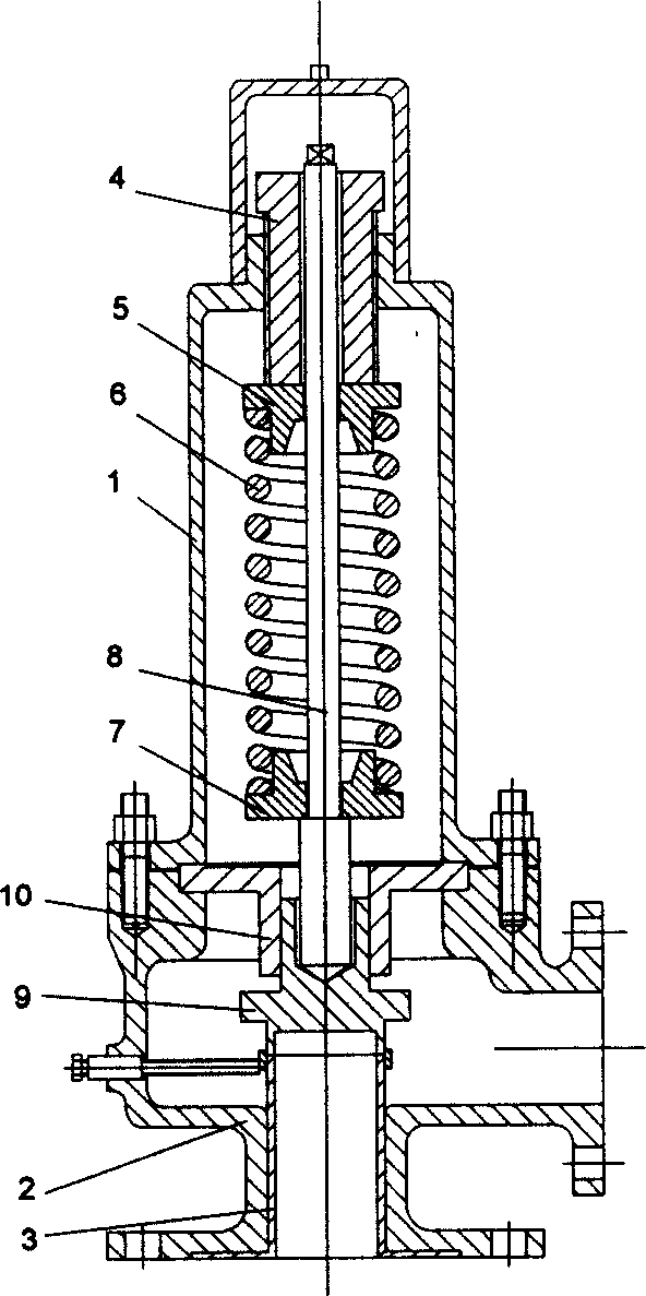
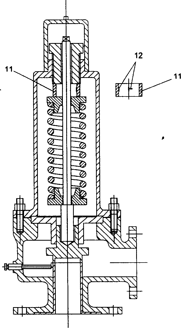
[0060] figure 1 The specific structure of the existing micro-opening safety valve is shown, which is composed of figure 1 It can be seen that the existing micro-opening safety valve includes an upper valve body 1, a lower valve body 2, a valve seat 3, and a disc assembly. The upper valve body 1 and the lower valve body 2 are detachable fixed connection structures (bolt connection), The valve seat 3 and the disc assembly are located in the space formed by the upper valve body 1 and the lower valve body 2. , sealing flap 9, and valve flap overcoat 10 are connected to form. figure 2 The specific structure of the safety valve with online detection function of the present invention is shown, and the safety valve of the present invention consists of figure 1 The micro-opening safety valve shown is transformed from figure 2 It can be seen that the safety valve is equipped with a force-measuring ring 11 axisymmetrically between the adjusting nut 4 and the upper compression ring 5...

Embodiment 2

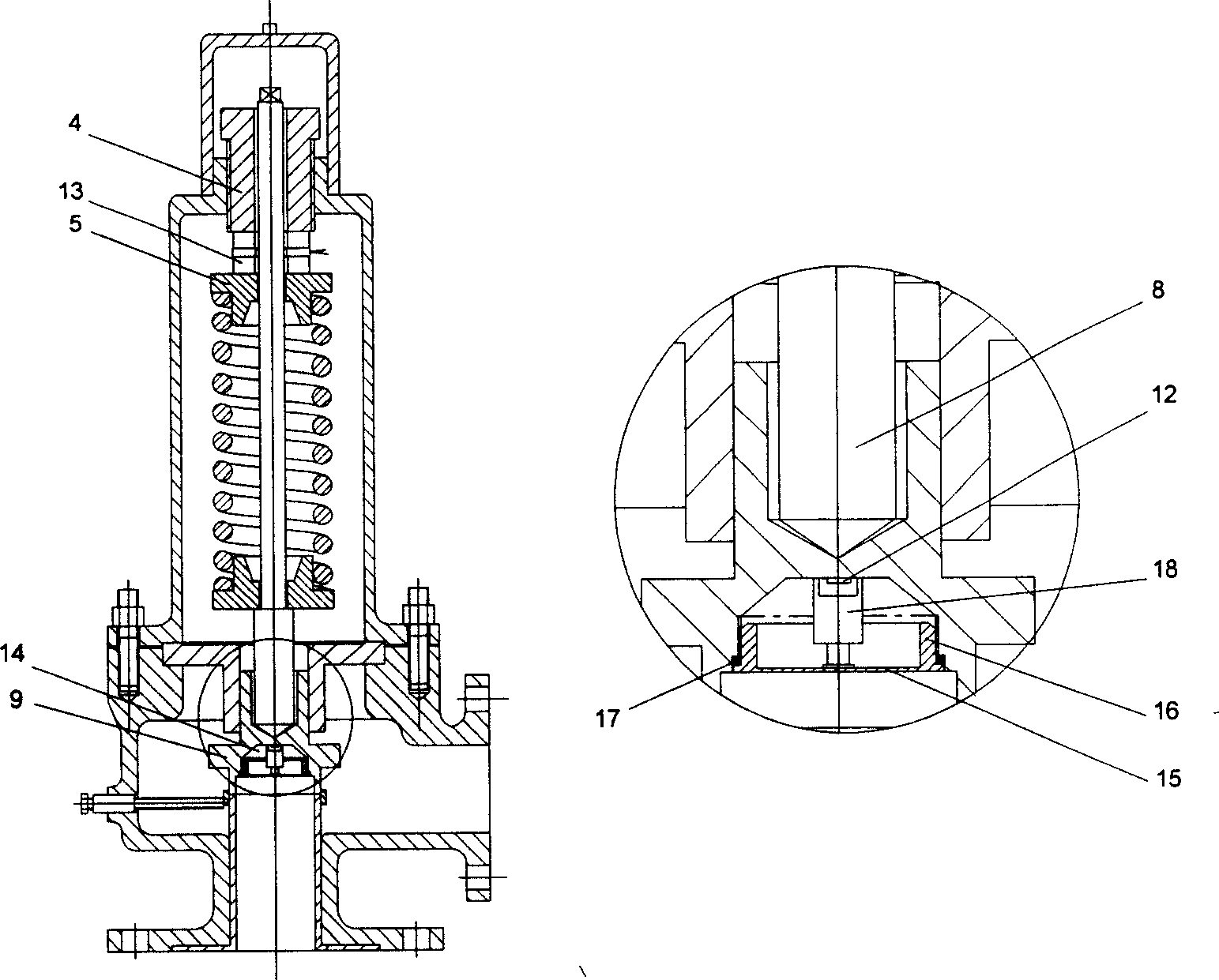
[0062] Another structure of the safety valve with on-line detection function of the present invention is as image 3 shown by image 3 It can be seen that, on the one hand, the safety valve is figure 1A piezoelectric sensor 13 is arranged axially symmetrically between the adjusting nut 4 and the upper compression ring 5 of the micro-opening safety valve shown to monitor the change of the spring force. On the other hand, the sealing flap 9 of the valve flap assembly One end connected to the installation equipment is provided with a concave hole 14 in the form of a conical cone and a cylinder, the opening of the concave hole 14 is provided with a pressure-bearing diaphragm 15, and the pressure-bearing diaphragm 15 is connected with a threaded ring 16 (with external thread) , the cylindrical part of the concave hole 14 is provided with an internal thread, the pressure-bearing diaphragm 15 is threadedly connected with the cylindrical part of the concave hole 14 through a threaded...

Embodiment 3

[0064] The specific structure of this embodiment is as Figure 4 As shown, this safety valve is the same as Embodiment 1 except for the following features: a stepped cylindrical concave hole 14 is provided at the end where the sealing flap 9 of the valve flap assembly is connected to the installation equipment, and a bearing is provided at the opening of the concave hole 14. Press the diaphragm 15, the pressure-bearing diaphragm 15 is connected with a threaded ring 16 (provided with an internal thread), the smaller cylindrical part of the concave hole 14 is provided with an internal thread, and another stepped cylinder 19 passes through the small end. The external thread is connected with the internal thread of the concave hole 14, and the stepped cylinder 19 is connected with the threaded ring 16 of the pressure-bearing diaphragm 15 through the external thread of the larger end, thereby fixing the pressure-bearing diaphragm 15 in the concave hole 14, a sealing ring 17 is prov...


PUM


Abstract

This invention provides a safety valve with on-line detecting function, which comprises upper valve body, lower valve body, valve seat and flap assembly, wherein the upper and lower valve body are dismountable fixed connecting structure, the valve seat and flap assembly are in the space formed by the upper and lower valve body; the flap assembly comprise sealing flap, valve rod, spring, upper clamp ring and lower clamp ring; inside the safety valve also has a sensor fitted in the flap assembly. When locating a sensing element on the internals, it will be integrated with the safety valve, or being an inner detecting element providing state variable parameter of the measured, or change the working element to monitoring element, by which can increase the safety of using kinds of pressure devices.

Description

technical field [0001] The invention relates to a safety device, in particular to a safety valve with an online detection function and a detection system thereof. Background technique [0002] Safety valves are the most widely used safety devices in pressure vessels, boilers and pipeline safety devices. When the pressure of the medium in the pressure vessel rises above the specified value for some reason, the force of the pressure medium on the disc of the internal components of the safety valve is greater than the force produced by the internal spring or other components of the valve, and the valve automatically opens to discharge Pressure medium to prevent the pressure in the pressure vessel, boiler or pipeline from rising further; when the pressure of the medium in the pressure vessel drops to a certain value due to the discharge of the safety valve, the force generated by the inner spring or other components of the safety valve is greater th...

Claims


Application Information

Patent Timeline
IPC IPC(8): F16K17/04
Inventor 郭崇志
Owner SOUTH CHINA UNIV OF TECH
Learn More