Digital tracking method of synchronous phase angle

A synchronous phase and digital technology, applied in the automatic control of power, electrical components, etc., can solve the difficulties of low-pass digital filter parameter design and transfer function analysis, increase the complexity and cost of the control system, occupy large system resources, etc. problem, to achieve the effect of simple design, eliminating time error and simplifying the processing process

Inactive Publication Date: 2005-11-30
TSINGHUA UNIV
View PDF1 Cites 4 Cited by
  • Summary
  • Abstract
  • Description
  • Claims
  • Application Information

AI Technical Summary

Problems solved by technology

[0004] The implementation of the existing digital phase-locked loop needs to include multiple links such as digital phase detector, digital filter, numerical control oscillator and feedback frequency divider, which is more complicated to realize, and the parameter design of low-pass digital filter and Transfer function analysis is more difficult
In the digital control system that needs to synchronize the grid voltage, if the digital phase-locked loop chip is used, the complexity and cost of the control system design will be increased. If the digital phase-locked loop is implemented in the FPGA, it will need to occupy a large system resource

Method used


Image

  • Digital tracking method of synchronous phase angle
  • Digital tracking method of synchronous phase angle
  • Digital tracking method of synchronous phase angle

Examples


Embodiment Construction

[0034] The digital tracking method of the synchronous phase angle proposed by the present invention includes the following steps: the following will be described in conjunction with the accompanying drawings.

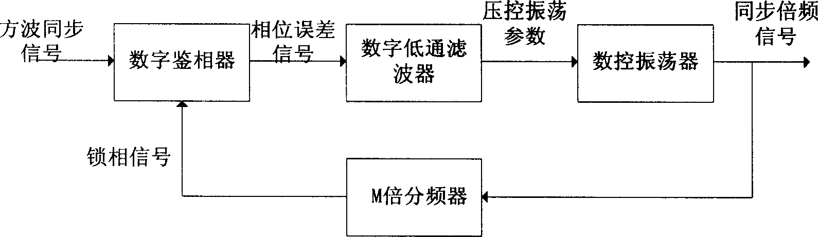
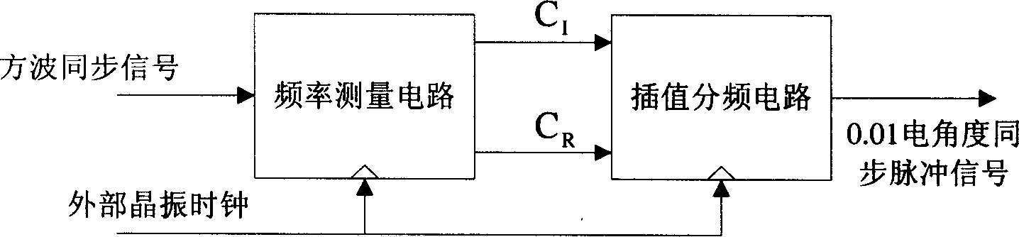
[0035] The principle block diagram of the synchronous phase angle digital tracking method of the present invention is as figure 2 shown. The input of the present invention is a square wave synchronous signal, whose rising edge is synchronized with the positive zero-crossing point of the grid voltage, and the time between the two rising edges is the power frequency period T of the grid voltage 1 . In order to accurately synchronize the output synchronous phase angle signal with the frequency of the grid voltage, it is necessary to use an external crystal oscillator clock signal to digitally track the frequency of the square wave synchronous signal. A power frequency cycle T 1 Corresponding to 360 electrical angles, in the present invention, the time corresponding to ...


PUM


Abstract

This invention relates to simultaneous phase angle digital tracing method in the relative technique field and is characterized by the following: first inputting the simultaneous signals into radio measurement circuit to get the frequency division of outer crystal clock of CI and plug parameters of CR; then using the CI, CR as frequency division values input to the plug and division circuit.

Description

technical field [0001] The invention relates to a digital tracking method for a synchronous phase angle. The method can perform precise frequency and phase tracking on an input square wave synchronous signal, and produce an accurate 0.01 electrical angle synchronous pulse signal output, belonging to the technical field of phase tracking. Background technique [0002] In the control field of electrical engineering, such as static var generators, active filters, dynamic voltage restorers and other devices, various control processes usually need to accurately track the frequency and phase of the grid voltage. With the development of digital signal processors (hereinafter referred to as DSP) and programmable logic gate arrays (hereinafter referred to as FPGA), full digital control has become an inevitable trend, and the frequency and phase of the grid voltage are accurately digitally tracked and the synchronous phase angle is obtained. A digital output is already necessary. [...

Claims


Application Information

Patent Timeline
Patent Type & Authority Applications(China)
IPC IPC(8): H03L7/06
Inventor 宋强刘文华
Owner TSINGHUA UNIV
Why Eureka
Try Eureka