Optical switch, optical modulator and variable wavelength filter

A technology of optical modulator and optical switch, which is applied in the direction of light guide, optics, instruments, etc., can solve the problem of high power supply price

Inactive Publication Date: 2005-12-07
NIPPON TELEGRAPH & TELEPHONE CORP
View PDF1 Cites 25 Cited by
  • Summary
  • Abstract
  • Description
  • Claims
  • Application Information

AI Technical Summary

Problems solved by technology

Therefore, in this case, the price of the existing power supply that can be used is very high

Method used


Image

  • Optical switch, optical modulator and variable wavelength filter
  • Optical switch, optical modulator and variable wavelength filter
  • Optical switch, optical modulator and variable wavelength filter

Examples


Embodiment approach 1

[0091] The optical switch of Embodiment 1 has an optical waveguide through which light propagates, and electrodes for applying an electric field to the optical waveguide. Dielectric crystals having cubic crystals such as KTN and KLTN crystals and having a large secondary electro-optic effect are used as the optical waveguide.

[0092] As a specific configuration, there is a Mach-Zehnder interferometer type optical switch capable of switching with a small change in refractive index, that is, capable of switching at a low driving voltage. In order to perform polarization-independent operation in this optical switch, it is necessary that the refractive index changes due to the secondary electro-optic effect be exactly equal in the TE direction and the TM direction. In the KTN and KLTN crystals used in this embodiment, the refractive index changes in the TE direction and the TM direction have an equal electric field orientation in principle. That is, by configuring electrodes tha...

Embodiment 1

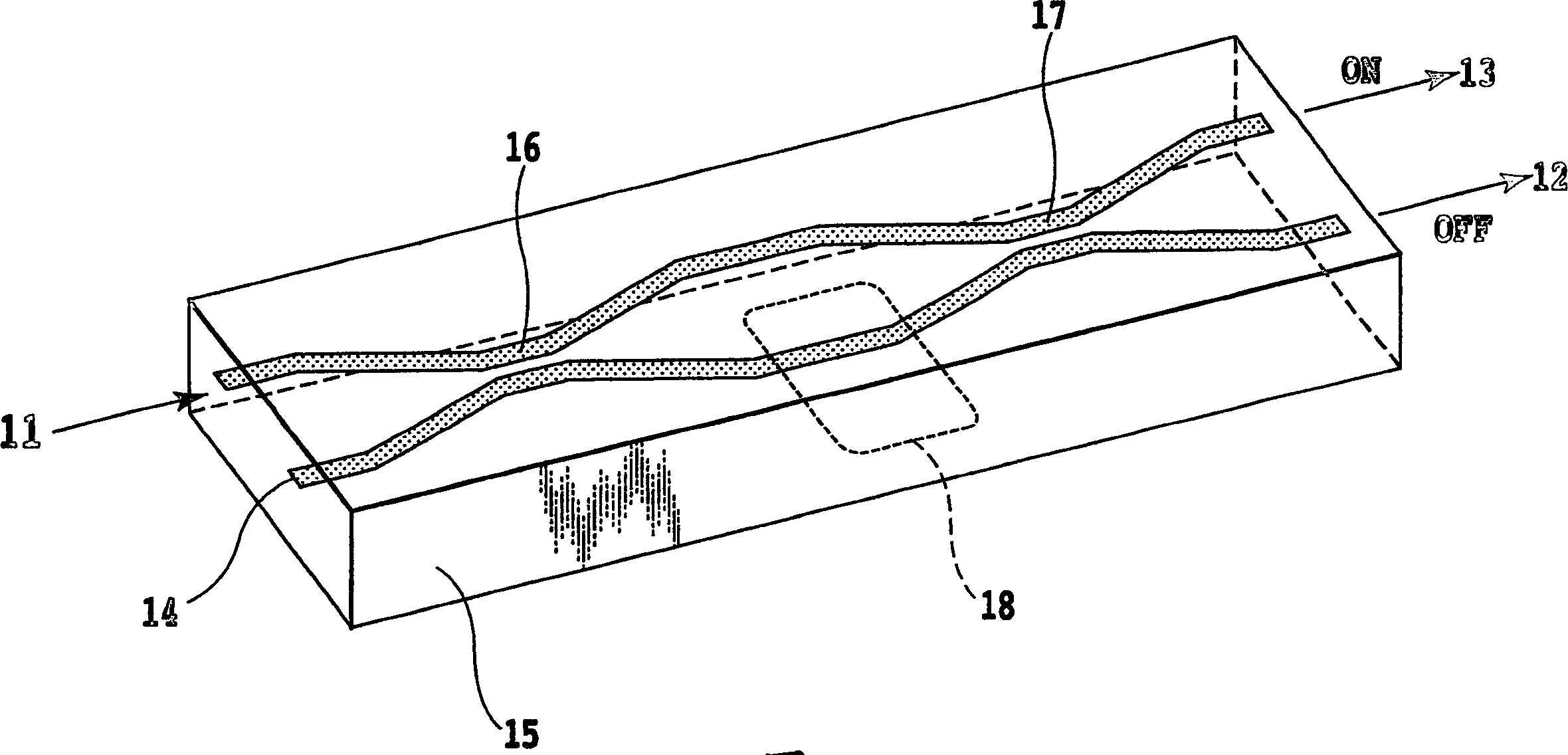
[0096] figure 1 It is a configuration diagram showing an example of an optical switch according to an embodiment of the present invention. The optical switch has a Mach-Zehnder interferometer. The optical waveguide of the optical switch is made of dielectric crystal. In addition, in other examples of this embodiment, it is also possible to have figure 1 The illustration is based on the optical switch of the Mach-Zehnder interferometer shown.

[0097] like figure 1 Shown, the optical switch of the present invention is to comprise the 3dB coupler 16 that is arranged on the input side, the 3dB coupler 17 that is arranged on the output side, 2 optical waveguides that connect the input side 3dB coupler 16 and the output side 3dB coupler 17 A Mach-Zehnder interferometer composed of branch waveguides). In addition, an electrode for applying an electric field to one of the two optical waveguides is provided as the phase adjustment unit 18 . In addition, the coupling constants of...

Embodiment 2

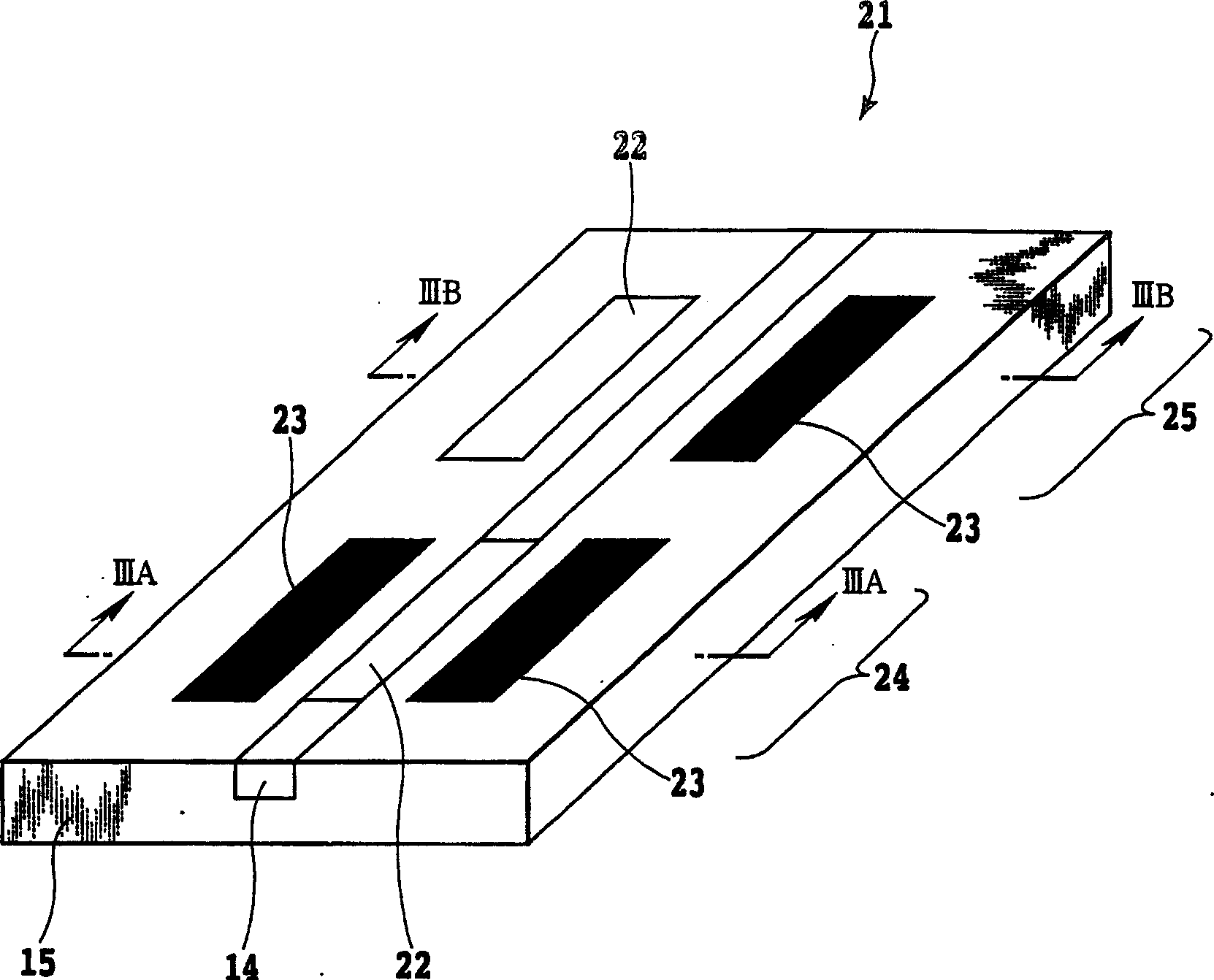
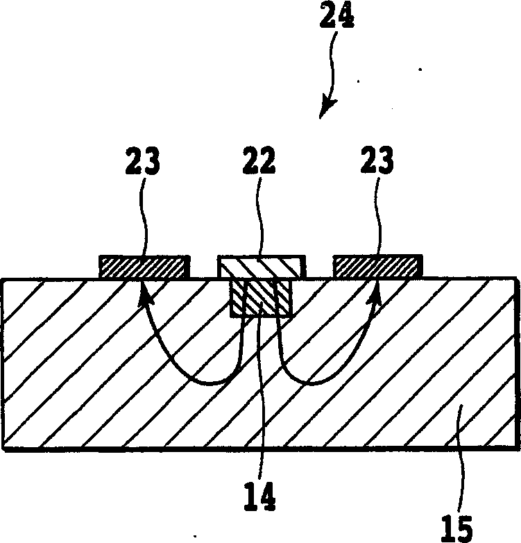
[0114] The structure of the optical switch of the present embodiment is that one side of the optical waveguide (branch waveguide) of the Mach-Zehnder interferometer is provided with figure 2 The phase modulation unit 24 of the phase modulation section 18 is shown, and the phase modulation unit 25 of the phase modulation section 8 is provided on the other side. Other configurations are substantially the same as those of the optical switch of the first embodiment. In this example, an optical switch having such a structure was produced and its operation was confirmed.

[0115] In the structure of the optical switch of the first embodiment, since the electric field is applied only to the branch waveguide of one side of the Mach-Zehnder interferometer, the change of the refractive index is the addition of equations (1) and (2). As explained in Example 1, the 2nd order electro-optic constants of KTN and KLTN crystals have opposite signs in the orthogonal direction. Therefore, alt...


PUM

PropertyMeasurementUnit
electro-optic coefficientaaaaaaaaaa
wavelengthaaaaaaaaaa
lengthaaaaaaaaaa

Abstract

A high-speed optical switch simple in structure, low in drive voltage and polarization-independent, an optical modulator, and a variable wavelength filter. The optical switch comprises a 3dB coupler (16) provided on the input side thereof, a 3dB coupler (17) provided on the output side, and two optical waveguides that connect the input-side 3dB coupler with the output-side 3dB coupler. In addition, a phase modulator (18) for applying an electric field to one or both of the two optical waveguides in provided. At least two optical waveguides consist of a crystal material having a composition consisting of KTa1-xNbxO3 (0 G02F 1 / 313 G02F 1 / 035 46 50 10 2004 / 3 / 18 1705908 2005 / 12 / 7 100410796 2008 / 8 / 13 2008 / 8 / 13 2008 / 8 / 13 Nippon Telegraph & Telephone Japan Enbutsu Koji Fujiura Kazuo Fushimi Hiroshi Imai Tadayuki Kurihara Takashi Matsuura Touru Sasaura Masahiro Shimokozono Makoto Tate Akiyuki Toyota Seiji li zheng yang xiaoguang 11247 Japan 2003 / 3 / 19 075105 / 2003 Japan 2003 / 3 / 20 077142 / 2003 Japan 2003 / 7 / 16 275521 / 2003 Japan 2003 / 8 / 28 305023 / 2003 Japan 2003 / 12 / 8 409658 / 2003 Japan 2003 / 12 / 11 412951 / 2003 2005 / 5 / 27 PCT / JP2004 / 003665 2004 / 3 / 18 WO2004 / 083953 2004 / 9 / 30 Japanese

Description

technical field [0001] The present invention relates to an optical switch, an optical modulator and a variable wavelength filter used in components for optical communication. Background technique [0002] Today, the demand for larger capacity, higher speed, and higher performance of optical communication systems is rapidly increasing. An optical switch or an optical modulator is expected as an optical signal processing device used in such an optical communication system. In particular, the importance of switches for optical cross-connects for network performance enhancement in recent years is rapidly increasing. As such an optical switch, an optical switch using a micromechanical technology called MEMS (Micro Electro Mechanical System) and an optical switch using a thermo-optical effect of a quartz-based optical waveguide have been developed. In addition, an optical switch that switches the optical path by filling the intersection of the waveguide with oil having the same ...

Claims


Application Information

Patent Timeline
Patent Type & Authority Applications(China)
IPC IPC(8): G02F1/313
CPCG02F2203/50G02B6/12011G02F1/3136G02F1/0147G02B2006/12145G02F1/365G02F2201/124G02F1/3551G02F1/225G02B6/12023G02B2006/12142G02F1/3137G02F1/212G02F1/313
Inventor 丰田诚治藤浦和夫笹浦正弘圆佛晃次下小园真今井饮之馆彰之松浦彻栗原隆伏见浩
Owner NIPPON TELEGRAPH & TELEPHONE CORP
Why Eureka
Try Eureka