Inkjet recording head

An inkjet recording and nozzle technology, applied in printing and other fields, can solve the problems of reduced output, reduced reliability, and increased production cost of piezoelectric actuators

Active Publication Date: 2005-12-14
BROTHER KOGYO KK
View PDF4 Cites 4 Cited by
  • Summary
  • Abstract
  • Description
  • Claims
  • Application Information

AI Technical Summary

Problems solved by technology

Also, if the pitch of the supply wires is reduced, the production cost of the piezoelectric actuator is increased, the yield thereof is also reduced, and the reliability of the wires to be electrically connected to the individual electrodes to provide a driving voltage thereto is reduced.

Method used


Image

  • Inkjet recording head
  • Inkjet recording head
  • Inkjet recording head

Examples


Embodiment Construction

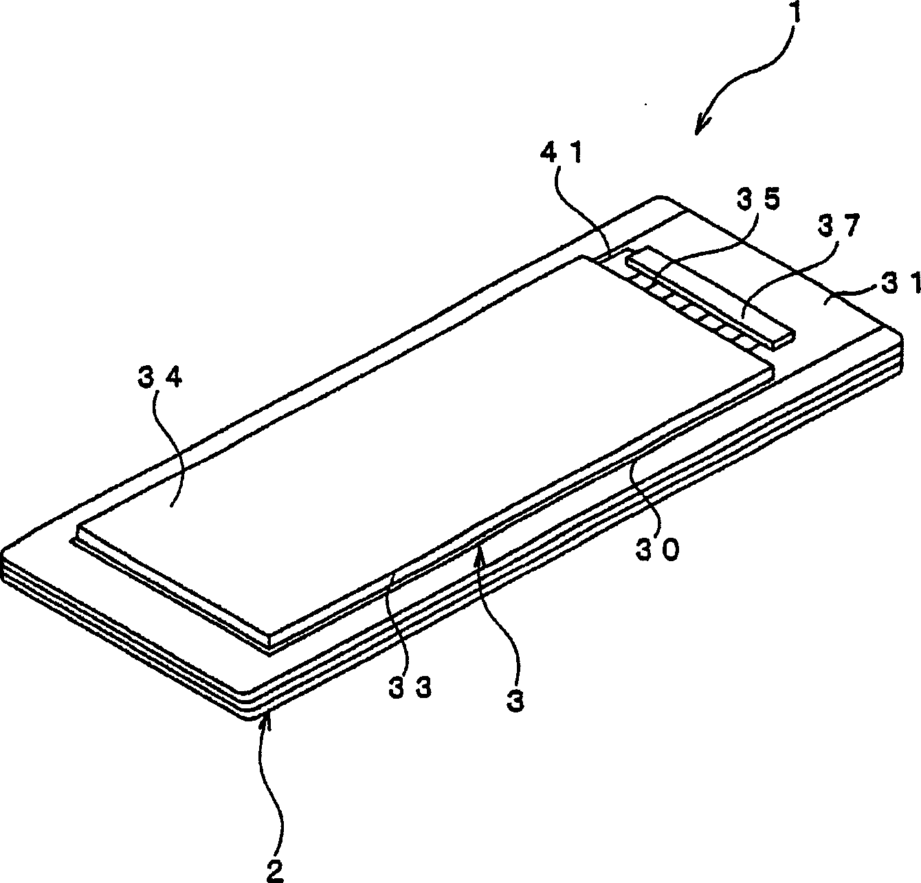
[0022] Hereinafter, preferred embodiments of the present invention will be described with reference to the accompanying drawings. Such as figure 1 As shown, an ink jet recording head 1 as an embodiment of the present invention includes a channel unit 2 in which a plurality of ink channels are formed; and a piezoelectric actuator 3 stacked on the upper surface of the channel unit 2 .

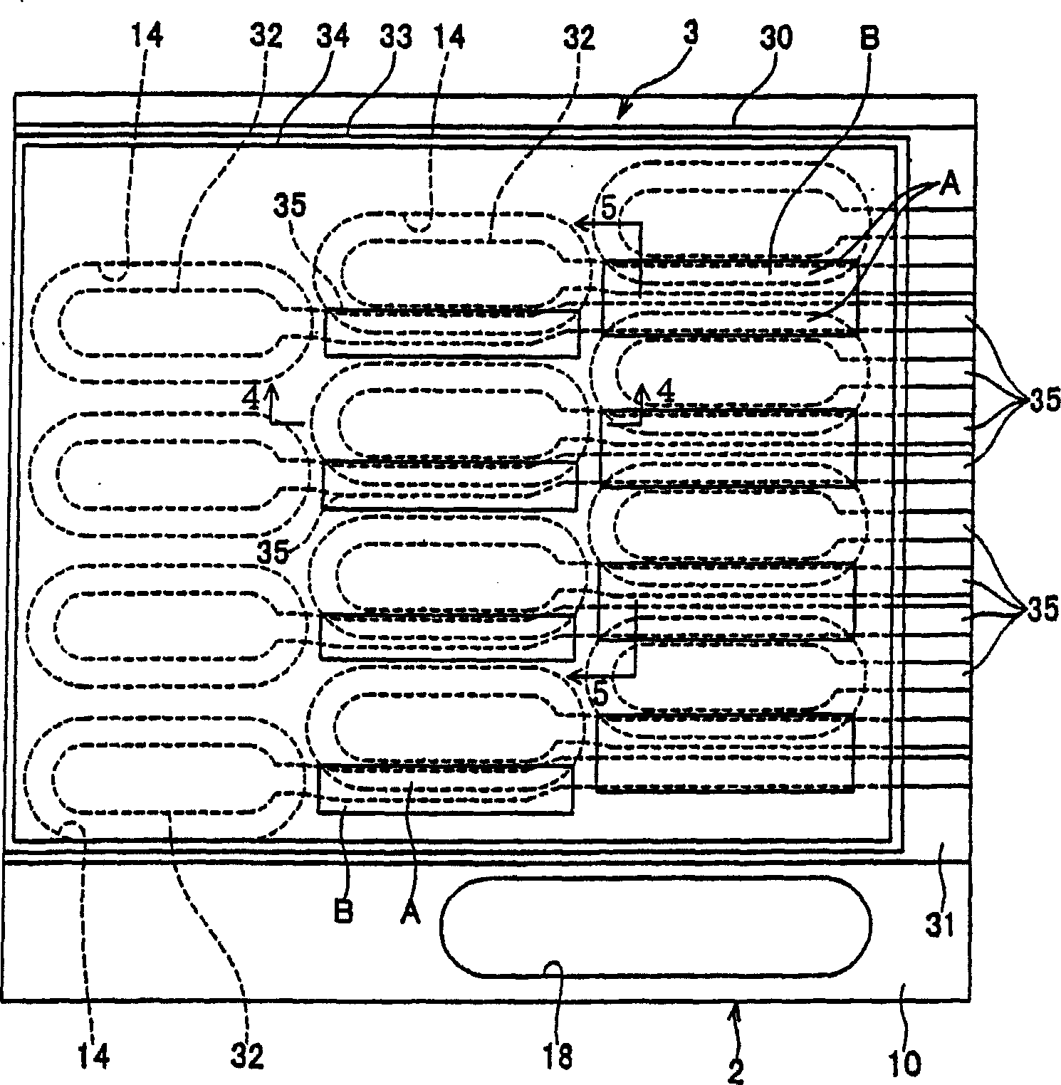
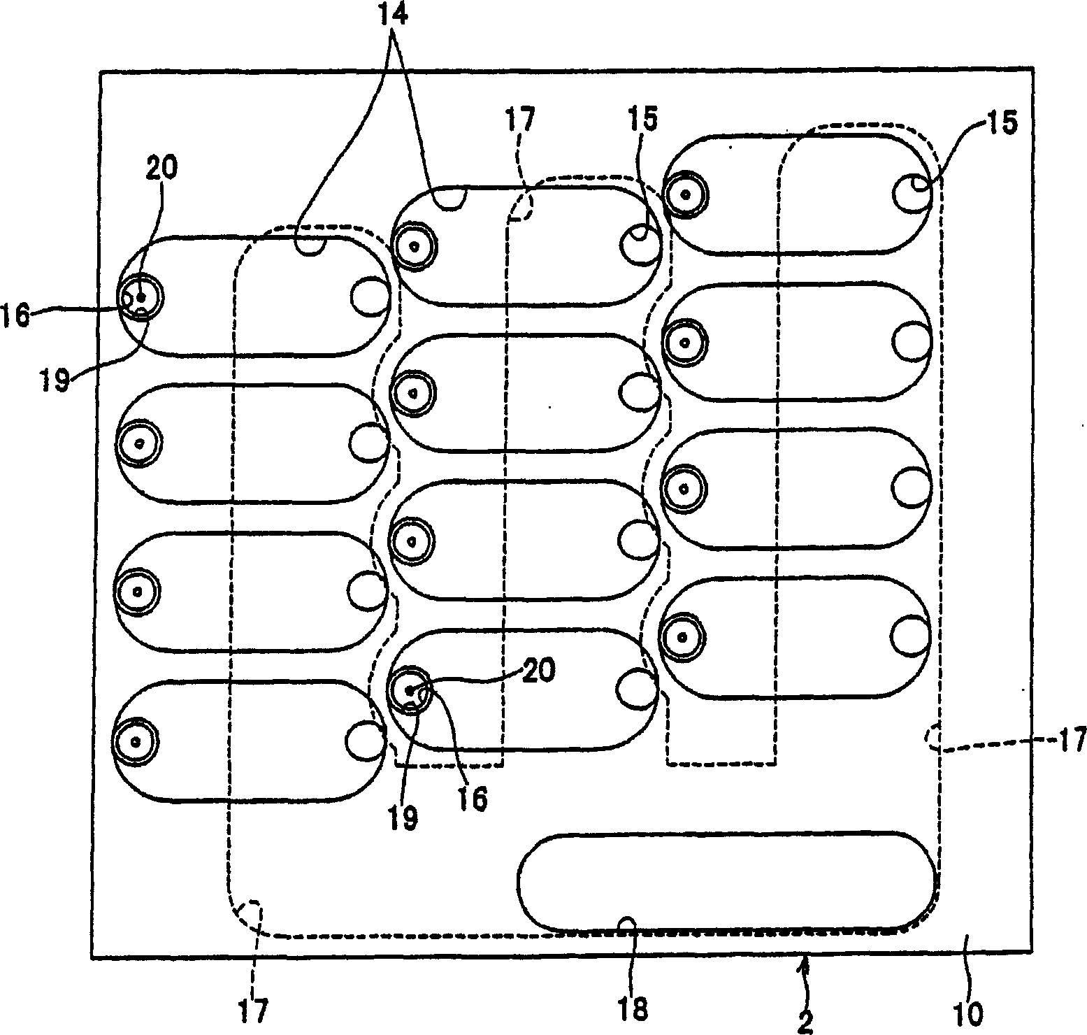
[0023] First, the channel unit 2 is described in detail. figure 2 yes figure 1 A schematic plan view of the right half of the inkjet recording head shown in ; image 3 yes figure 1 A schematic plan view of the right half of channel unit 2 represented in ; Figure 4 yes figure 2 A cross-sectional view of the inkjet recording head 1 along line 4-4; Figure 5 yes figure 2 A cross-sectional view of the ink jet recording head 1 along line 5-5. as in Figure 2-5 As shown, the channel unit 2 comprises a cavity sheet 10, a base sheet 11, a manifold sheet 12 and a nozzle sheet 13 stacked and b...


PUM


Abstract

An inkjet recording head, comprising: a channel unit (2), which has a plurality of pressure chambers (14) respectively communicating with a plurality of nozzles (20) along a reference plane, and each nozzle ejects small ink droplets; Electric actuators (3; 40; 50; 55; 60), which change the volume of any one of the pressure chambers, so that a corresponding nozzle ejects small ink droplets, wherein the piezoelectric actuators include: respectively corresponding to a plurality of pressure chambers A plurality of individual electrodes (32; 62), a common electrode (34; 44; 61) opposite each individual electrode, a piezoelectric layer (33; 63) interposed between the individual electrodes and the common electrode, and A plurality of electric wires (35; 65) respectively connected to a plurality of independent electrodes to respectively provide driving voltages to the independent electrodes, and wherein viewed from a direction perpendicular to the reference plane, connected to at least one first pressure chamber corresponding to the pressure chamber A portion (A; C) of at least one wire of at least one first individual electrode of the individual electrodes overlaps a portion of at least one second pressure chamber of a pressure chamber different from the at least one first pressure chamber.

Description

[0001] This application is based on Japanese Patent Application No. 2004-169280 filed on June 8, 2004, the contents of which are incorporated herein by reference. technical field [0002] The present invention relates to an inkjet recording head that ejects ink to a recording medium and thereby performs recording on the medium. Background technique [0003] Patent Document 1 (Japanese Patent Application Laid-Open No. 2003-159798) or Patent Document 2 (Japanese Patent No. 3267937 and its corresponding US Patent No. 6471342) discloses an inkjet recording head which ejects ink to a recording medium and thereby Record on this medium. The disclosed inkjet recording head includes: a channel unit having a plurality of pressure chambers respectively communicating with a plurality of nozzles; and a piezoelectric actuator selectively changing the volume or volume of any one or more pressure chambers. respective volumes. The piezoelectric actuator includes a plurality of independent ...

Claims


Application Information

Patent Timeline
IPC IPC(8): B41J2/045B41J2/055B41J2/14
CPCB41J2/14233B41J2002/14266B41J2002/14459B41J2002/14491
Inventor 菅原宏人
Owner BROTHER KOGYO KK
Why Eureka
Try Eureka