Super high frequency conjoined multi-cavity paster media wave filter

A dielectric filter and ultra-high frequency technology, which is applied to waveguide devices, electrical components, circuits, etc., can solve the problems of ultra-high frequency dielectric filter signal interference, inconvenient adjustment of center frequency and electrical performance, etc.

Inactive Publication Date: 2005-12-14
严盛喜
View PDF0 Cites 7 Cited by
  • Summary
  • Abstract
  • Description
  • Claims
  • Application Information

AI Technical Summary

Problems solved by technology

[0007] The purpose of the present invention is to provide an ultra-high frequency conjoined multi-cavity chip dielectric filter, which overcomes the shortcomings of the previous ultra-high frequency dielectri

Method used


Image

  • Super high frequency conjoined multi-cavity paster media wave filter
  • Super high frequency conjoined multi-cavity paster media wave filter
  • Super high frequency conjoined multi-cavity paster media wave filter

Examples


Embodiment Construction

[0029] The center frequency f of the ultra-high frequency conjoined multi-cavity patch dielectric filter of the present invention o The frequency range is: 400MHz~5.8GHz. The input impedance and output impedance of this dielectric filter are equal, and its value Zc is 50 ohms. The passband width of this dielectric filter is f o ±3MHz, that is, 6MHz.

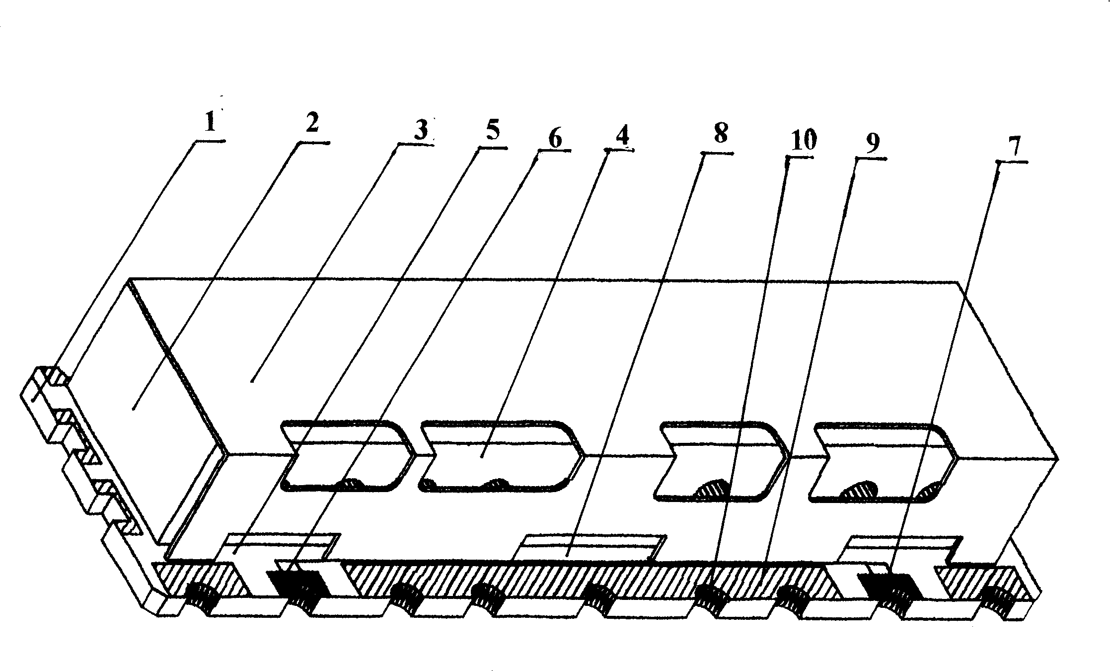
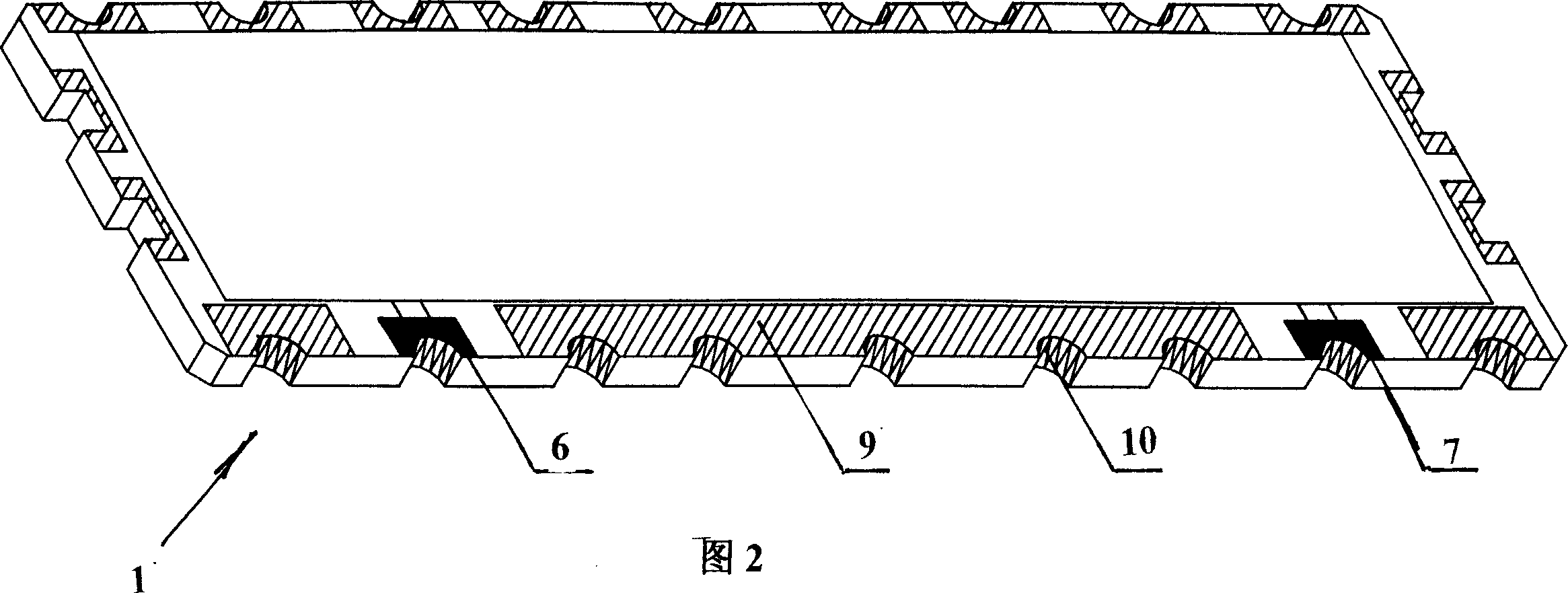
[0030] see figure 1 : In this high-frequency conjoined multi-cavity patch dielectric filter outline structure diagram, the bottom plane of the conjoined multi-cavity dielectric filter (2) is welded on the upper surface of the printed circuit board (1), and the upper surface of the shielding shell (3) The inner surface of the inner surface is welded on the upper surface of the assembled multi-cavity dielectric filter (2), and there are some rectangular through holes of different sizes ( 4), a rectangular through hole (5) is opened near the left and right ends of the lower front side of the shielding shell (3), and a middle rect...


PUM


Abstract

The multi-cavity UHF dielectric filter with several connected dielectric blocks is one kind of electronic device. The UHF dielectric filter consists of printed circuit board, dielectric filter and shielding casing. The dielectric filter is welded to the printed circuit board, and the shielding casing has its upper plane welded on ground electrode, front side bottom edge welded to the ground of the printed circuit board, and rectangular through holes. Owing to the shielding casing, the UHF dielectric filter has high interference immunity and easy electric performance regulation.

Description

Technical field: [0001] The ultra-high frequency conjoined multi-cavity patch dielectric filter of the present invention is an electronic component, which can adjust the electrical performance of its ultra-high frequency filter, and can shield interference signals, and is directly mounted on a printed circuit board. It belongs to A multi-cavity patch filter composed of multiple dielectric blocks. Background technique: [0002] After the input signal passes through the filter circuit, the frequency components that do not need to pass in the signal can be filtered out, and the dielectric filter is a passive filter circuit, which is composed of passive filter components such as resistors, capacitors, and inductors. The values ​​of these passive components and their circuit connections determine the resonant frequency. For this reason, band-pass filters, high-pass and low-pass filters, and band-stop filters can be designed. [0003] If each dielectric block is connected in seri...

Claims


Application Information

Patent Timeline
IPC IPC(8): H01P1/208
Inventor 严盛喜
Owner 严盛喜
Why Eureka
Try Eureka