Beam combiner

A light source controller, light source technology, applied in the coupling of optical waveguides, instruments, optics, etc., can solve the problems of increasing light power, cost and space, cost constraints, etc., and achieve a solid mechanical structure, easy to clean, and low price. Effect

Inactive Publication Date: 2004-05-26
LUMINIT
View PDF0 Cites 7 Cited by
  • Summary
  • Abstract
  • Description
  • Claims
  • Application Information

AI Technical Summary

Problems solved by technology

[0003] Unfortunately, many existing lighting systems do not provide sufficient power for a wide range of applications
In addition, increasing the power of light for a large number of applications is limited by cost and space
For example, high-speed data transmission through the atmosphere will be limited by cost due to the necessary power requirements
Moreover, in many applications such as object positioning systems, the use of large lighting systems is restricted by price and size.
For example, the highest power laser diodes available cannot produce more than 1 to 4 watts of power
However, under atmospheric conditions with low visibility, this power is not enough to realize the three-dimensional reproduction of the battlefield scene

Method used


Image

  • Beam combiner
  • Beam combiner
  • Beam combiner

Examples


Embodiment Construction

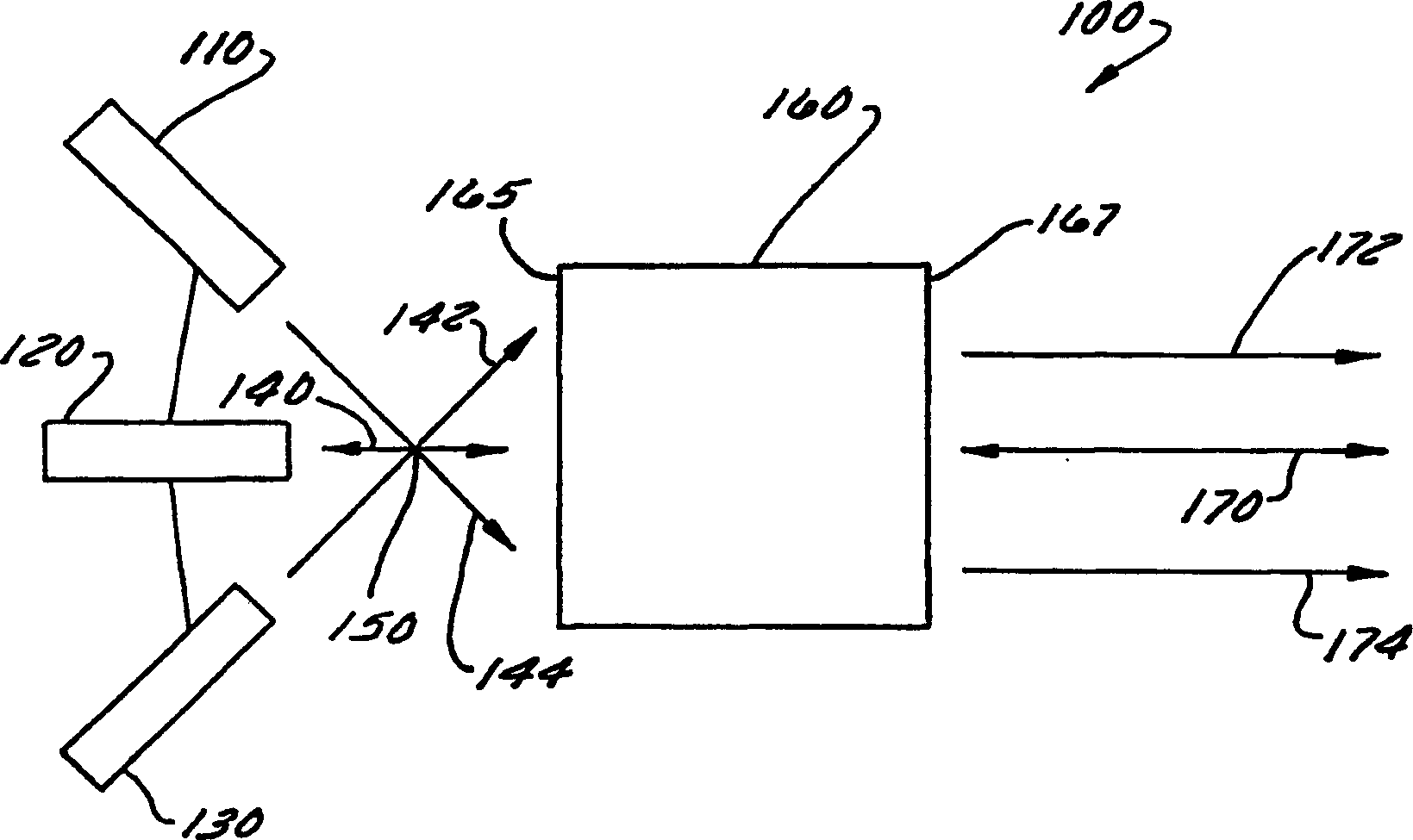
[0037] figure 1It is a block diagram of a system or device 100, such as NIBCC, for combining and collimating light passing through the atmosphere, according to a first embodiment. Apparatus 100 includes light sources 110 , 120 , 130 and non-imaging element (NIE) 160 . The light sources 110 , 120 and 130 include at least two light sources 110 , 130 or more than two light sources 110 , 130 . The light sources 110, 120, and 130 may also include fiber light sources, optical fibers, gradient index lenses, fiber lasers, laser diodes, or any other devices used as light sources. NIE 160 includes an entrance face 162 and an exit face 167 . NIE 160 includes means to collimate and / or combine light. In operation, light sources 110 , 120 and 130 emit light 140 , 142 and 144 directly toward the entrance face of NIE 160 . At least two of the plurality of light sources emit light of substantially equal wavelengths. Lights 140, 142, and 144 pass through focal point 150 and are directed en...


PUM


Abstract

A nonimaging beam combiner and collimator. The nonimaging beam combiner and collimator can include at least two light sources (110, 130) that emit light of the same wavelength (142, 144) through a focus point (150) and a nonimaging element (160) that receives the light of the same wavelength after the focus point and collimates the light at the same wavelength through the atmosphere. The at least two light sources (110, 130) can include fiber light sources, optical fibers, gradient index lenses, fiber lasers or laser diodes. The nonimaging element (160) can include an input surface (165), a paraboloid surface located adjacent to the input surface, a conical surface located adjacent to the paraboloid surface, and an ellipsoid surface located adjacent to the conical surface and located on an opposite side of the nonimaging element (160) from the input surface (165). The paraboloid surface can include a total internal reflection surface.

Description

technical field [0001] The present invention relates to a beam converging device, in particular to a method and device for combining and collimating light passing through the atmosphere. Background technique [0002] Lighting systems are currently available to transmit light. This transmitted light is used to communicate data between the light source and receiver. For example, data can be transmitted from a source to a receiver via an optical fiber. In addition, this transmitted light can be used to localize objects. For example a laser sight is used to aim at a target. Furthermore, transmitted light can also be used for engraving. High-power radars can use the transmission of light, for example, for target illumination. [0003] Unfortunately, many existing lighting systems do not provide sufficient power for a wide variety of applications. In addition, increasing the power of light for a large number of applications is limited by cost and space. For example, high-sp...

Claims


Application Information

Patent Timeline
Patent Type & Authority Applications(China)
IPC IPC(8): G02B6/32G02B6/43G02B27/00G02B27/10G02B27/30H04J14/02
CPCG02B6/43G02B27/30G02B27/126G02B27/123G02B27/1073H04J14/02H04B10/00
Inventor 伊利亚·阿古若克朗尼·林塞
Owner LUMINIT
Why Eureka
Try Eureka