Intelligent energy mixer

A pneumatic and intelligent technology, applied in the field of intelligent pneumatic mixing device, can solve the problems of low mixing efficiency, low filtration precision, and inability to realize intelligent centralized control of the system.

Inactive Publication Date: 2005-12-28
JIANGSU NDZ TECH
View PDF4 Cites 6 Cited by
  • Summary
  • Abstract
  • Description
  • Claims
  • Application Information

AI Technical Summary

Problems solved by technology

However, these devices generally have the defects of low filtration accuracy, poor dust removal effect, low mixing efficiency, and inability to adapt to the processing requirements of materials with different physical and chemical characteristics, and cannot realize intelligent centralized control of the system

Method used


Image

  • Intelligent energy mixer
  • Intelligent energy mixer
  • Intelligent energy mixer

Examples


Embodiment Construction

[0010] The present invention will be described in further detail below in conjunction with the accompanying drawings and embodiments.

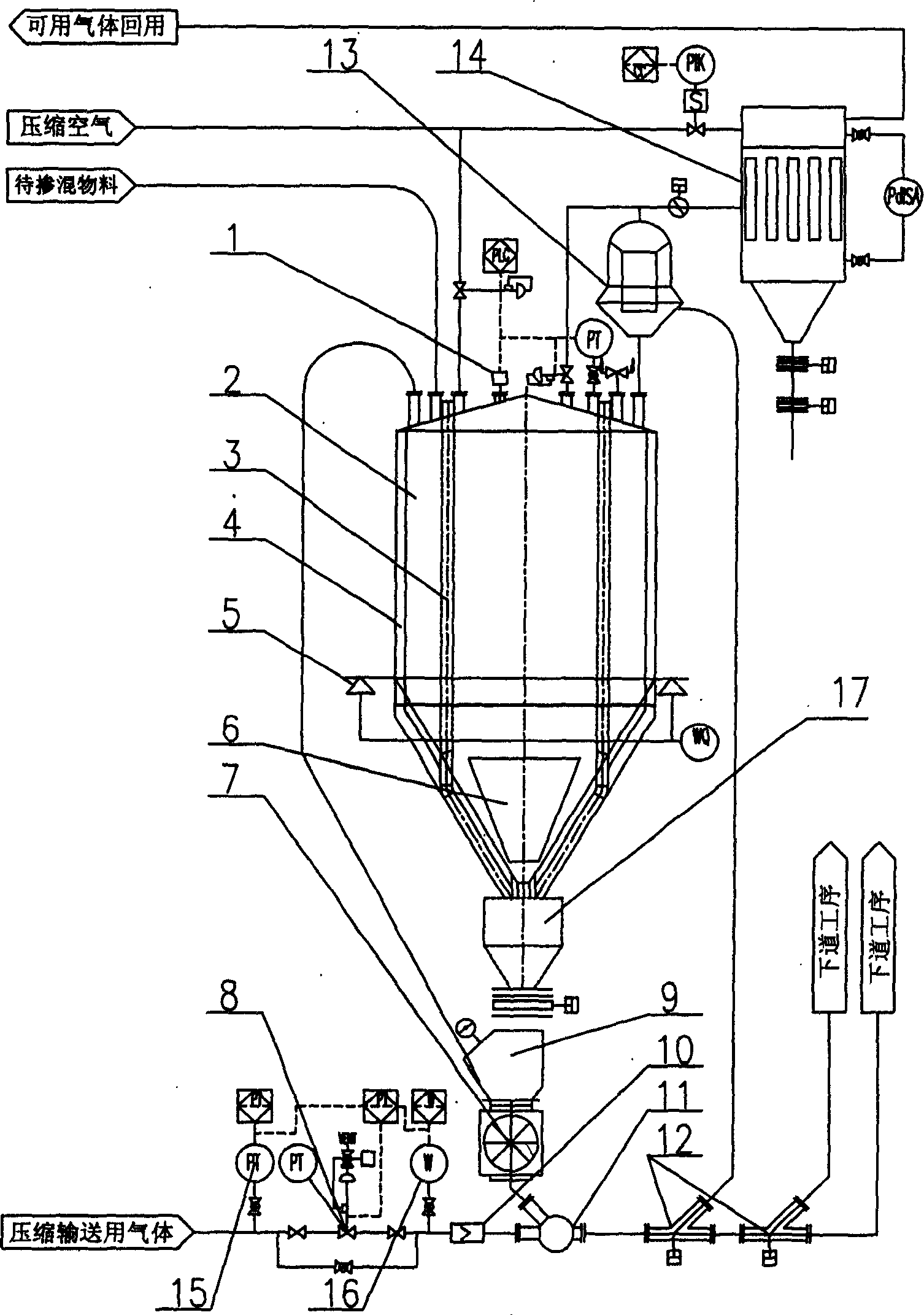
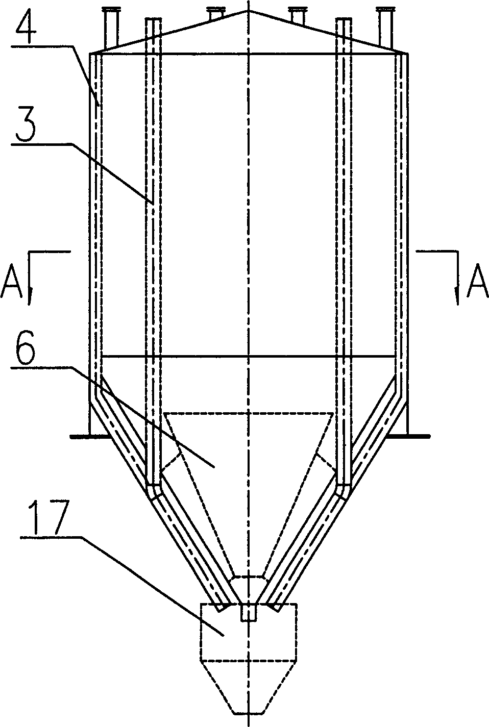
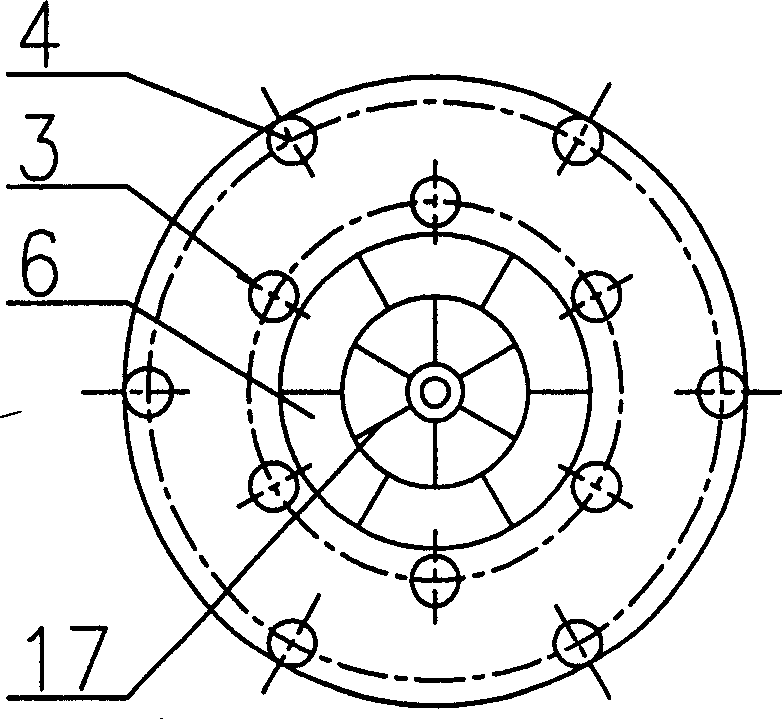
[0011] Such as Figure 1~3 As shown, an intelligent pneumatic blending device includes a blending silo 2, a jet injection pipe 11 and a material conveying pipeline, and also includes a high-pressure feeding device 7, a high-pressure feeding pipe valve 12, a multi-stage volute and multi-cone diffuser Separator 13 and high-pressure pulse dust collector 14, the bottom of blending bin 2 is connected with blending chamber 17, and blending bin 2 communicates with blending chamber 17, the bottom of blending bin 2 is inverted cone, and A multi-cone mixing and spreading device 6 is arranged on the inverted cone of the blending silo 2. There are multiple central tubes 3 and multiple wall-adhering tubes 4 in the mixing silo 2, and the wall-attaching tubes 4 pass through the delivery pipeline and the high-pressure The feeding device 7 communicates, and t...


PUM


Abstract

An intelligent pneumatic mixer is composed of raw material mixing cabin with multiple central pipes and multiple peripheral pipes close to wall, jet spray pipe, material delivering pipeline, high-pressure feeder, valve for high-pressure delivering pipe, multi-stage multi-conic diffusion separator with volute casing, and high-pressure pulse duster.

Description

technical field [0001] The invention relates to a conveying device for different batches of powder and granular materials produced in different time periods, in particular to an intelligent pneumatic mixing device. Background technique [0002] In the process of industrial mass production, in order to meet the relatively stable physical and chemical characteristics requirements of different batches of powder and granular related materials produced in different time periods, it is necessary to blend this material. The blending form in the case of non-mechanical direct contact is basically the form of pneumatic conveying. The transportation of powder and granular materials is involved in many industries such as petrochemical, grain, oil and feed, mining metallurgy, warehousing and logistics. In many respects, pneumatic conveying has incomparable advantages compared with other mechanical conveying: it can improve the crushing fineness and crushing efficiency in pneumatic negat...

Claims


Application Information

Patent Timeline
Patent Type & Authority Applications(China)
IPC IPC(8): B01F33/40
Inventor 虞兰剑陶志康张志斌
Owner JIANGSU NDZ TECH
Why Eureka
Try Eureka