Excited quasi-molecular lampbulb
A technology of excimer lamps and outer tubes, which is applied in the direction of discharge lamps, discharge tubes/lamps, components of gas discharge lamps, etc., and can solve the problems of reducing light, insufficient uniformity, light reduction and uniformity, etc. problem, to achieve the effect of reducing the amount of light, deteriorating the uniformity, stabilizing and homogenizing the discharge
- Summary
- Abstract
- Description
- Claims
- Application Information
AI Technical Summary
Problems solved by technology
Method used
Image
Examples
Embodiment 1
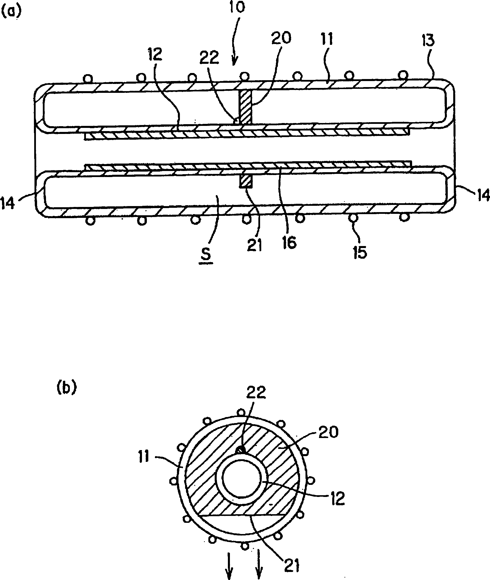
[0028] exist figure 1 Among them, (a) is a sectional view in the pipe axis direction, and (b) is a sectional view in the radial direction.
[0029] Between the outer tube 11 and the inner tube 12 in the discharge space S, a support plate 20 is provided to fit the inner tube 12. As shown in (b), on the support plate 20, toward the direction of the light extraction part, In the illustrated case, the notch 21 is formed downward. The notch 21 is cut as large as possible so as to support the inner tube 12 with respect to the outer tube 11 without being obstructive.
[0030] The above-mentioned support plate 20 is inserted into the inner tube, and a part thereof is welded or bonded 22 to the inner tube 12 to restrict movement around the inner tube 12 in the rotational direction and in the axial direction.
Embodiment 2
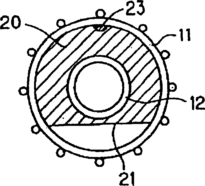
[0032] exist figure 2 In the second embodiment, the supporting plate 20 formed with the notch 21 is welded or bonded 23 to the outer tube 11 at a part of its outer circumference, and other than that, it is the same as the first embodiment.
[0033] As shown in Embodiment 1 and Embodiment 2 above, any one of the support plate 20 being welded or bonded to the inner tube 12 at the inner peripheral edge, or welded or bonded to the outer tube 11 at the outer peripheral edge can be used. When considering the assembly process of the discharge vessel 13, it is preferable that the support plate 20 is fixed to the inner tube 12 as shown in Embodiment 1.
[0034] That is, the assembly of the discharge vessel 13 is performed by inserting the support plate 20 into the outer tube 11 in a state where the support plate 20 is attached to the inner tube 12, and by joining the two at the ends, so that the support plate 20 is fixed on the inner tube 12. , the insertion into the outer tube 11 ca...
Embodiment 3
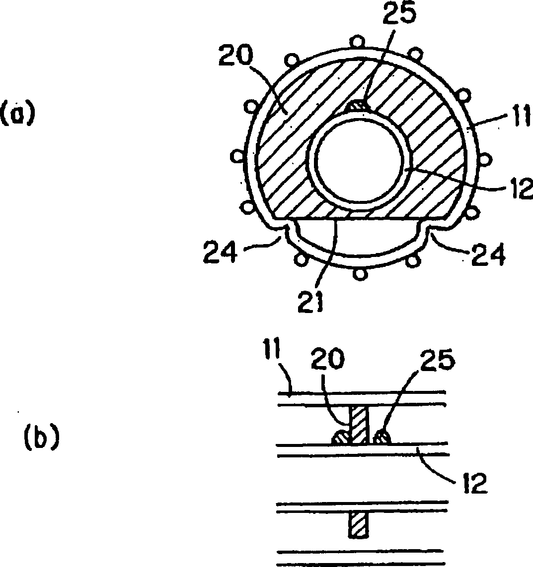
[0036] exist image 3 In Example 3, a recess 24 is formed in the outer tube 11 at a position below the notch 21 of the support plate 20 . The recess 24 can be formed by pressing the rod-shaped body after baking and softening the outer tube 11 with a burner. At this time, the recess 24 acts to lift the support plate 20 upward in the discharge space S, that is, toward the upper inner surface of the outer tube 11 , and presses the support plate 20 toward the outer tube 11 . The recess 24 restricts movement of the support plate 20 in the rotational direction.
[0037] Further, small protrusions 25 formed on both sides of the support plate 20 are formed on the inner tube 12 to restrict movement of the support plate 20 in the axial direction of the inner tube 12 . The small protrusions 25 are formed by heating and softening a quartz glass rod and welding it to the inner tube 12 .
[0038] In this third embodiment, the outer tube 11 of the support plate 20 is brought into contact ...
PUM
 Abstract
Description
Claims
Application Information
 - R&D
- Intellectual Property
- Life Sciences
- Materials
- Tech Scout
- Unparalleled Data Quality
- Higher Quality Content
- 60% Fewer Hallucinations
Browse by: Latest US Patents, China's latest patents, Technical Efficacy Thesaurus, Application Domain, Technology Topic, Popular Technical Reports.
© 2025 PatSnap. All rights reserved.Legal|Privacy policy|Modern Slavery Act Transparency Statement|Sitemap|About US| Contact US: help@patsnap.com


