
Correcting unit and method for mismatched phase-synchronized signal and orthogonal-phase signal

A matching correction and quadrature phase technology, which is applied in the field of correcting phase difference, can solve the problems of increasing circuit complexity, power loss, and increasing power consumption, and achieve the effect of reducing computing burden and system complexity

Active Publication Date: 2005-12-28
REALTEK SEMICON CORP
View PDF0 Cites 15 Cited by
  • Summary
  • Abstract
  • Description
  • Claims
  • Application Information

AI Technical Summary

Problems solved by technology

However, the operation of using discrete Fourier transform to calculate the phase offset δ not only requires complex logic circuits for complex logic calculations, but also increases additional power consumption
However, the digital circuit needs an external correction signal to perform the least mean square algorithm for compensation, which also increases the complexity and power loss of the circuit.

Method used


Image

  • Correcting unit and method for mismatched phase-synchronized signal and orthogonal-phase signal
  • Correcting unit and method for mismatched phase-synchronized signal and orthogonal-phase signal
  • Correcting unit and method for mismatched phase-synchronized signal and orthogonal-phase signal

Examples


Embodiment Construction

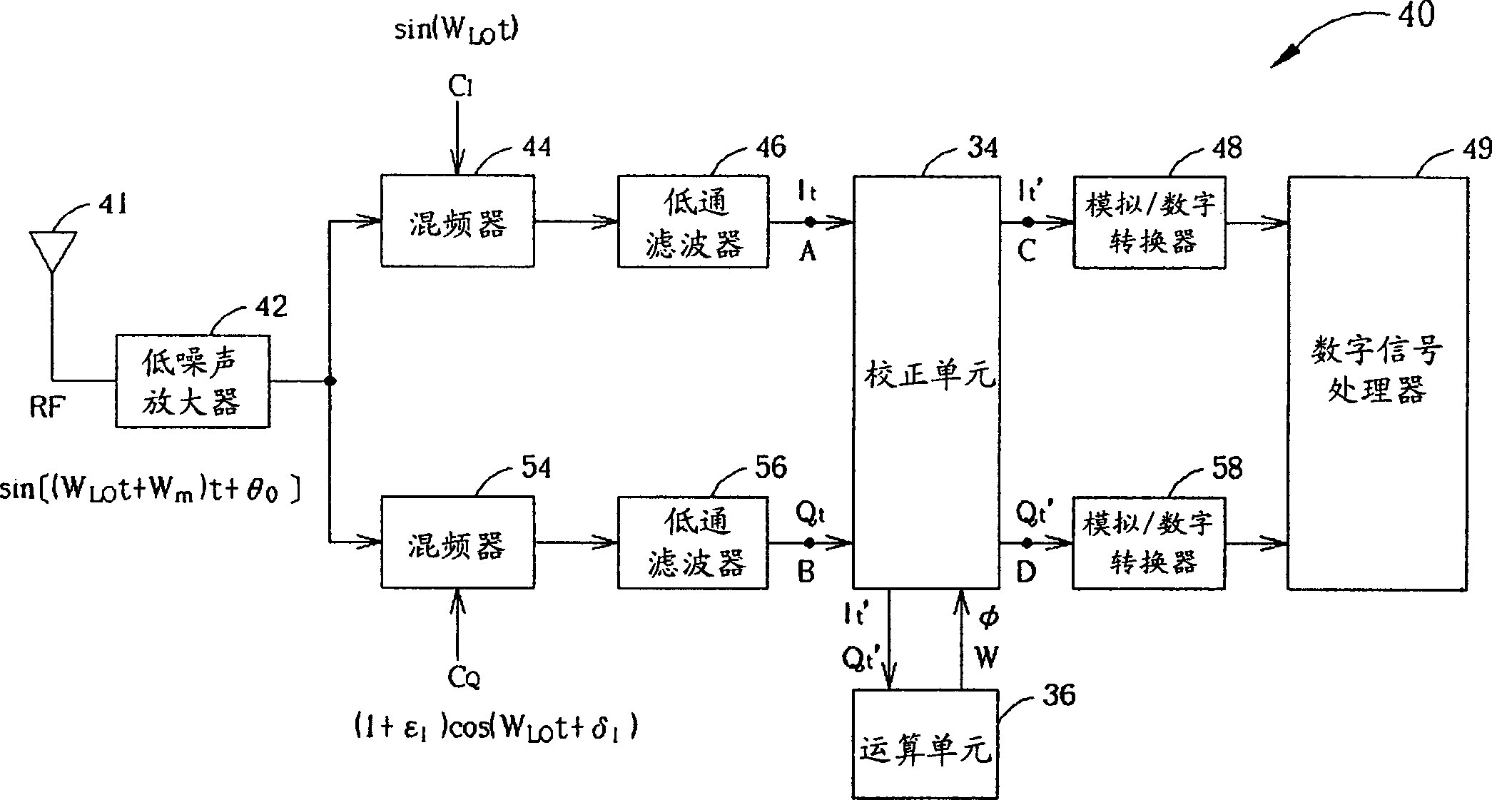
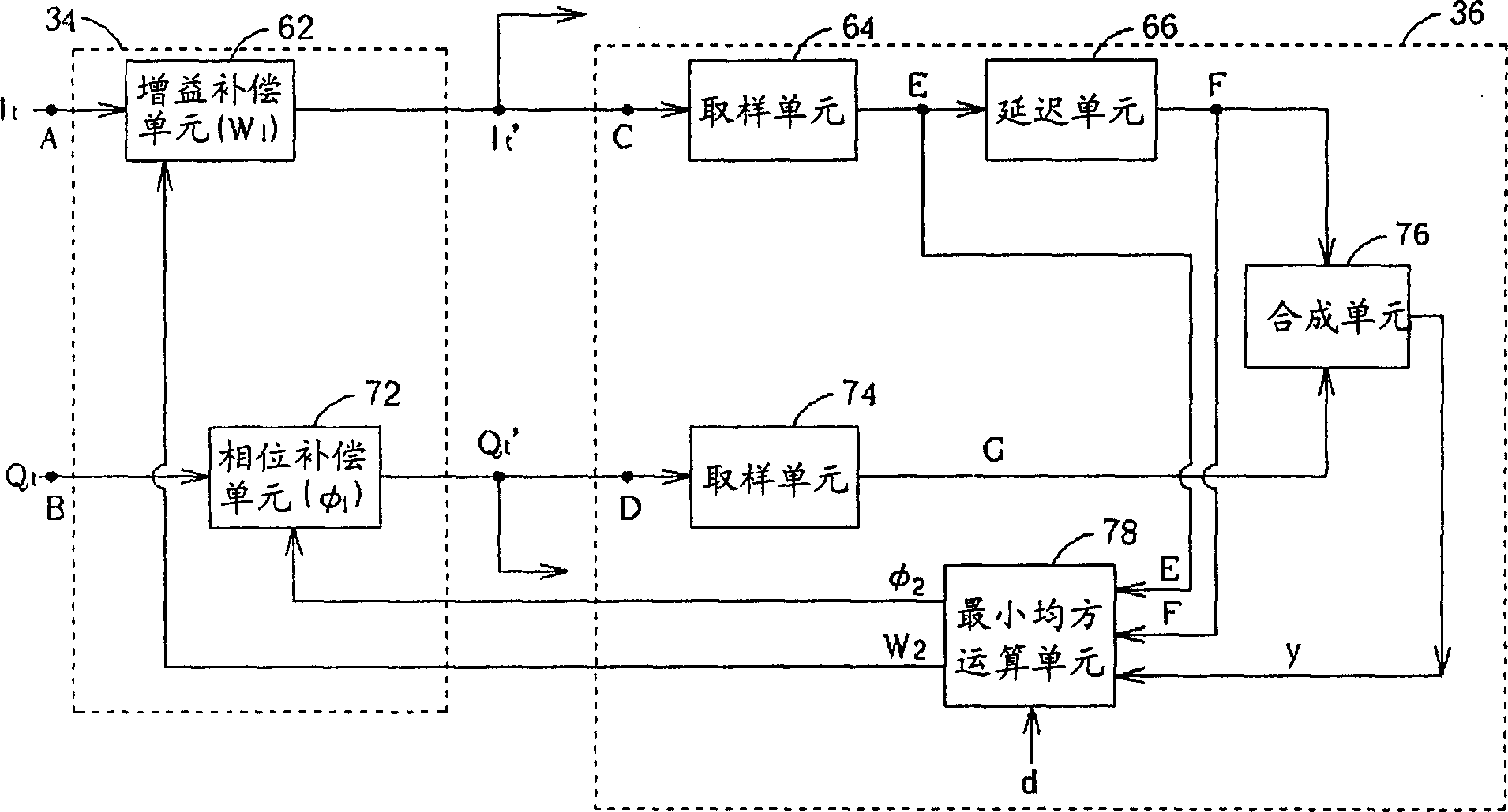
[0012] see figure 2 , figure 2 A schematic diagram of a transceiver (trahsceiver) 40 of a direct down-conversion architecture proposed by an embodiment of the present invention. The direct frequency down architecture transceiver 40 includes an antenna 41, a low noise amplifier 42, a plurality of mixers 44, 54 and a plurality of low pass filters 46, 56, and its function and implementation are similar to known direct frequency down The architecture of the transceivers is substantially the same and will not be repeated here. It should be noted that the mixer 44 utilizes the first carrier C I Direct-convert the RF signal to generate an in-phase analog signal I t . In addition, the mixer 54 utilizes the second carrier C Q Directly down-convert the RF signal to generate a quadrature-phase analog signal Q t . In this embodiment, the direct down frequency architecture transceiver 40 further includes a correction unit 34 for correcting the in-phase analog signal I t and quadr...


PUM


Abstract

The device consists of: a mixer used to generate in-phase analog signals based on in-phase carrier signals mixing RF signals; second mixer used to generate orthorhombic phase analog signals based on orthorhombic phase carrier signals mixing RF signals; correction unit used to make compensation for in-phase and orthorhombic phase analog signals by using in-phase, orthorhombic mismatching compensating signals, and to correct in-phase and orthorhombic phase mismatch between in-phase analog signals and orthorhombic analog signals; and arithmetic unit coupling with correction unit used to generate in-phase and orthorhombic phase mismatch compensating signals.

Description

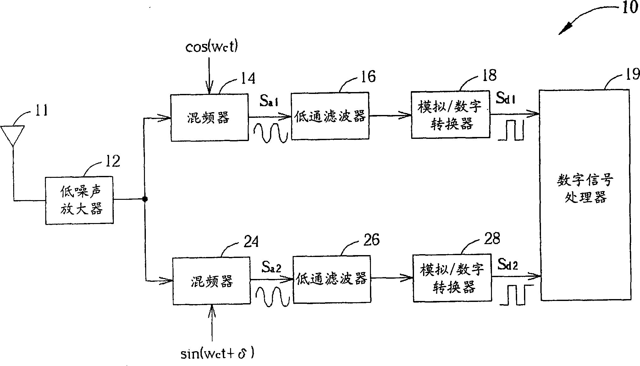
technical field [0001] The invention relates to a method and device for correcting phase difference, in particular to a method and device for correcting in-phase / quadrature phase mismatch of in-phase and quadrature-phase signals. Background technique [0002] see figure 1 , figure 1 is a schematic diagram of a known direct down-conversion architecture receiver 10 . The direct down-conversion receiver 10 includes an antenna 11, a low noise amplifier (LowNoise Amplifier, LNA) 12, mixers 14, 24, low-pass filters (LPF) 16, 26, analog / digital converter (ADC) 18 , 28, and a digital signal processor (Digital Signal Processor, DSP) 19. The antenna 11 receives a wireless communication signal, and the low noise amplifier 12 is used to amplify the wireless communication signal received by the antenna 11 . The mixer 14 combines the wireless communication signal with a first carrier (ie figure 1 COS ω shown c t) mixing to generate an analog signal S a1 , another mixer 24 mixes the...

Claims


Application Information

Patent Timeline
Patent Type & Authority Applications(China)
IPC IPC(8): H04B1/40
Inventor 李朝政林尹尧林盈熙
Owner REALTEK SEMICON CORP
Learn More