Split type permanent magnet synchronous wind driven electric generator

A wind turbine and permanent magnet synchronous technology, which is applied in the direction of wind turbine components, wind engines, wind motor combinations, etc., can solve the problems of inconvenient transportation and installation, shutdown maintenance, low power generation efficiency, etc., to reduce transportation and installation costs , Reduce the probability of failure, improve the effect of power generation efficiency

Inactive Publication Date: 2006-01-11
潍坊中云机器有限公司
View PDF0 Cites 13 Cited by
  • Summary
  • Abstract
  • Description
  • Claims
  • Application Information

AI Technical Summary

Problems solved by technology

[0003] When a synchronous generator is used, the speed of the wind turbine is required to be very stable. Therefore, a speed regulator with a complex structure must be used to automatically maintain a constant speed of the wind turbine, which makes the entire wind power generation device very complicated.
[0004] Regardless of whether synchronous generators or various asynchronous generators are used, the common disadvantages are: 1. The blades drive the speed-up mechanism, and the speed-up mechanism drives the generator to generate electricity. However, the speed-up mechanism is bulky and often occurs during operation. Oil leakage, tooth damage, damage to the box, etc. Once the above phenomena occur, it will cause leakage, pollute the environment, or shut down for maintenance and fail to generate electricity; 2. The power generation efficiency is very low at low wind speed, and at high wind speed It can't make full use of wind energy; 3. The noise is loud during operation
[0005] With the continuous advancement of technology, the power of a single high-power grid-connected wind turbine is increasing, its volume is becoming larger and heavier, and because the entire generator is a whole, it is necessary to use super large Transportation and installation can only be carried out with advanced transportation tools and lifting equipment, which not only increases the cost, but also brings a lot of inconvenience to transportation and installation
[0006] The streamlined external shape, due to its small turbulence and wake, when the wind acts on the blades, the force on the entire wind turbine is almost unidirectional. The unidirectional force will be very large and the stability will be poor

Method used


Image

  • Split type permanent magnet synchronous wind driven electric generator
  • Split type permanent magnet synchronous wind driven electric generator
  • Split type permanent magnet synchronous wind driven electric generator

Examples


Embodiment Construction

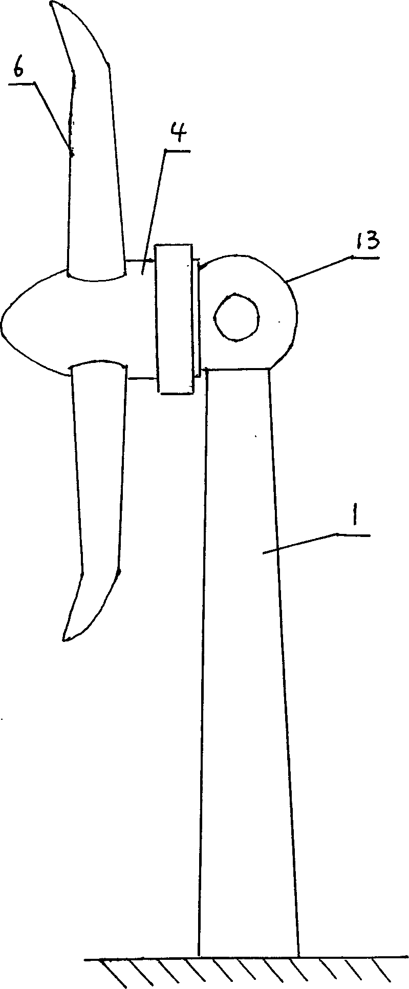
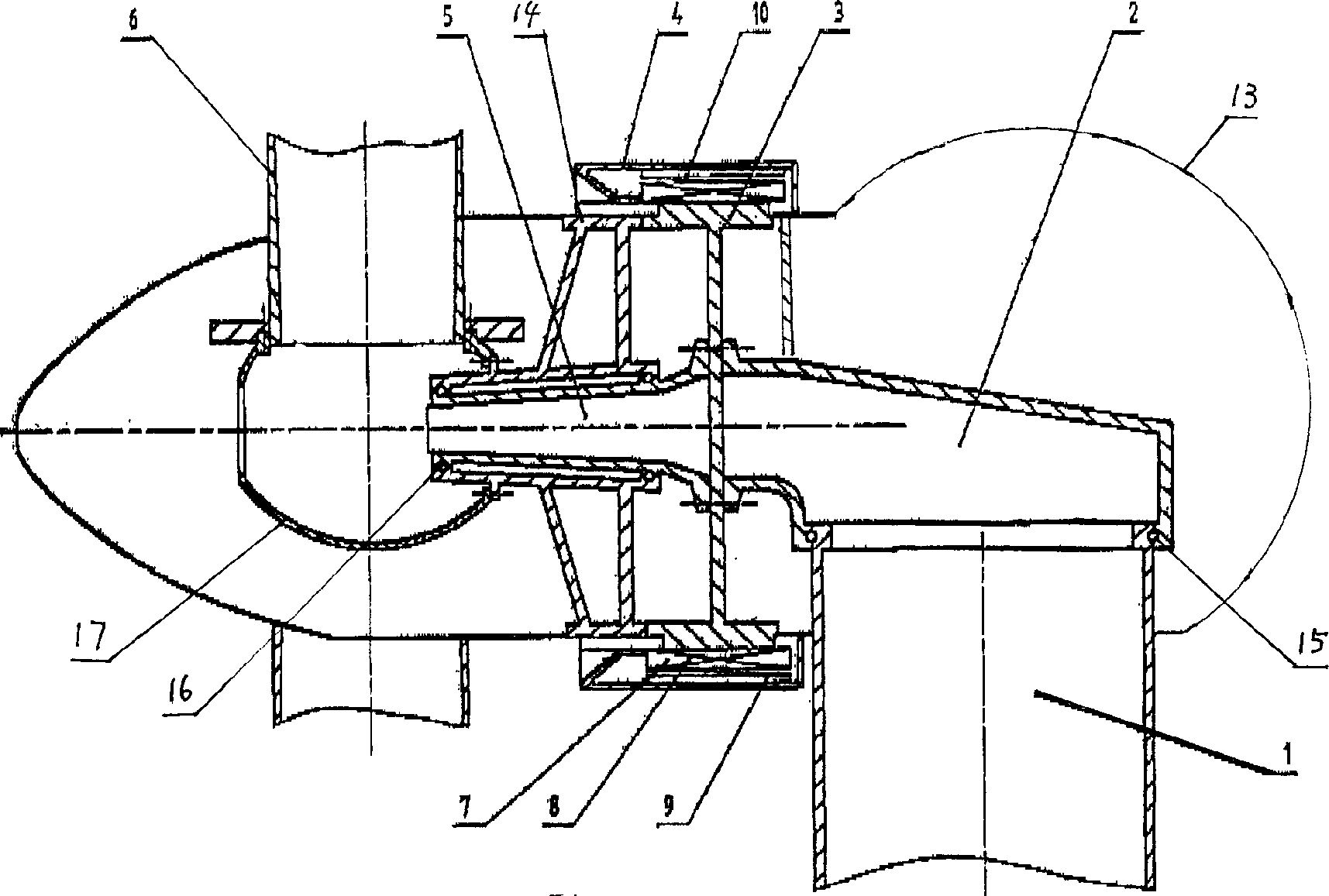
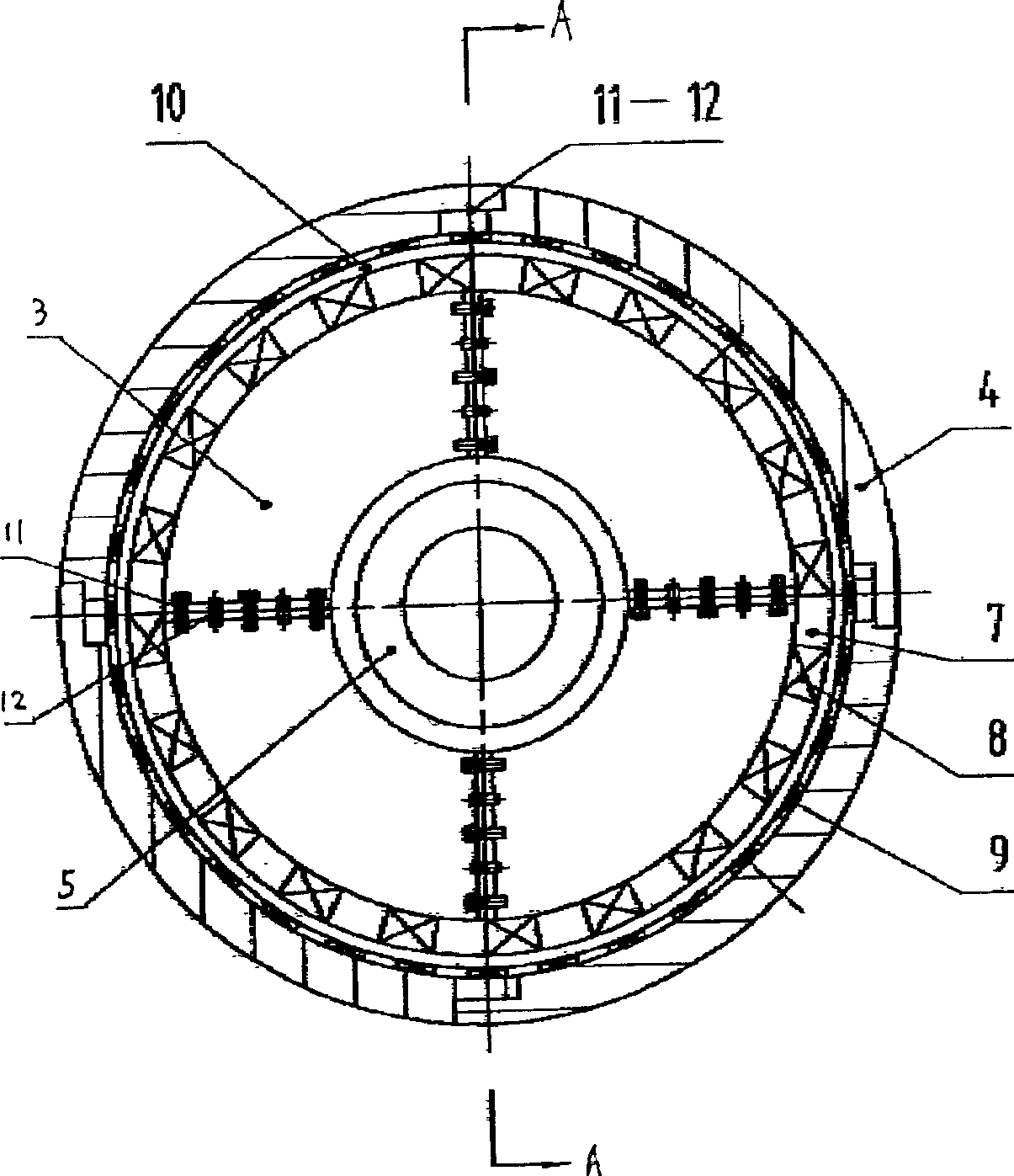
[0018] Referring to the accompanying drawings, the split type permanent magnet synchronous wind power generator described in the embodiment includes a tower 1, the upper end of the tower 1 is connected with a revolving body 2 through a bearing 15, and the revolving body 2 is fixedly connected in the inner cavity of the nacelle 13, The rear section of the nacelle 13 is in the shape of a hemispherical shell. The stator bracket 3 and the central shaft 5 are fixedly connected to the rotating body 2. The central shaft 5 is connected to the turntable 14 through the bearing 16. The rotor casing 4 is fixedly connected to the turntable 14. The rotor casing The blade end of 4 is streamlined, the blade 6 is fixedly connected to the turntable 14 through the hub 17, and the evenly distributed stator core 7 is inlaid on the circumferential surface of the stator bracket 3, and the three-phase coil winding 8 is wound on the stator core 7. A permanent magnet 9 is inlaid on the inside of the ann...


PUM


Abstract

The invention relates to a sectional permasyn wind-driven generator which consists of a tower, a gyrorotor connected on the top of the tower via a bearing in the inner cavity of the engine compartment, a stator stand and a central shaft jointed firmly on the gyrorotor a turntable communicated with the central shaft via the bearing, a rotor housing jointed firmly on the turntable, a vane fixed on the turntable via a hub, the uniform distributed stator core inlaid on the peripheral surface of the stator stand, a triphase coil winding on the stator core and a permanent-magnet inlaid on the inner ring surface of the rotor housing. There is an air-gap between the permanent-magnet and the stator core. The stator stand and rotor housing are separated. At least two sections are assembled together via the bolt and the internal screw cylindrical pin.

Description

technical field [0001] The invention relates to a wind power generator, more specifically to a split type permanent magnet synchronous wind power generator. Background technique [0002] The current high-power grid-connected wind turbines mainly use synchronous generators, asynchronous generators, two-speed asynchronous generators or double-fed asynchronous generators. The entire generator is a whole with a streamlined external shape. [0003] When a synchronous generator is used, the speed of the wind turbine is required to be very stable. Therefore, a speed regulator with a complex structure must be used to automatically maintain a constant speed of the wind turbine, which makes the entire wind power generation device very complicated. [0004] Regardless of whether synchronous generators or various asynchronous generators are used, the common disadvantages are: 1. The blades drive the speed-up mechanism, and the speed-up mechanism drives the generator to generate electric...

Claims


Application Information

Patent Timeline
Patent Type & Authority Applications(China)
IPC IPC(8): F03D11/04F03D11/00F03D9/00F03D9/25F03D13/20F03D80/70
CPCY02E10/728Y02E10/72
Inventor 陈亦栋张其智
Owner 潍坊中云机器有限公司
Why Eureka
Try Eureka