Diversity antenna assembly in wireless communication terminal

A technology for wireless communication terminals and diversity antennas, applied in diversity/multi-antenna systems, antenna supports/mounting devices, antennas, etc., can solve the problems that are not suitable for multi-antenna design of handheld devices and terminal applications, and achieve remarkable results Diversity effects, stable wireless link performance, and capacity-enhancing effects

Inactive Publication Date: 2006-02-01
UNIV OF ELECTRONIC SCI & TECH OF CHINA
View PDF3 Cites 16 Cited by
  • Summary
  • Abstract
  • Description
  • Claims
  • Application Information

AI Technical Summary

Problems solved by technology

In the Chinese patent CN 1411158A "diversity antenna and wireless communication equipment using it" granted to Naoko Umehara, etc., the annou

Method used


Image

  • Diversity antenna assembly in wireless communication terminal
  • Diversity antenna assembly in wireless communication terminal
  • Diversity antenna assembly in wireless communication terminal

Examples


Embodiment 1

[0065] Embodiment 1: Terminal Diversity Antenna with One Antenna Element and Orthogonal Feed

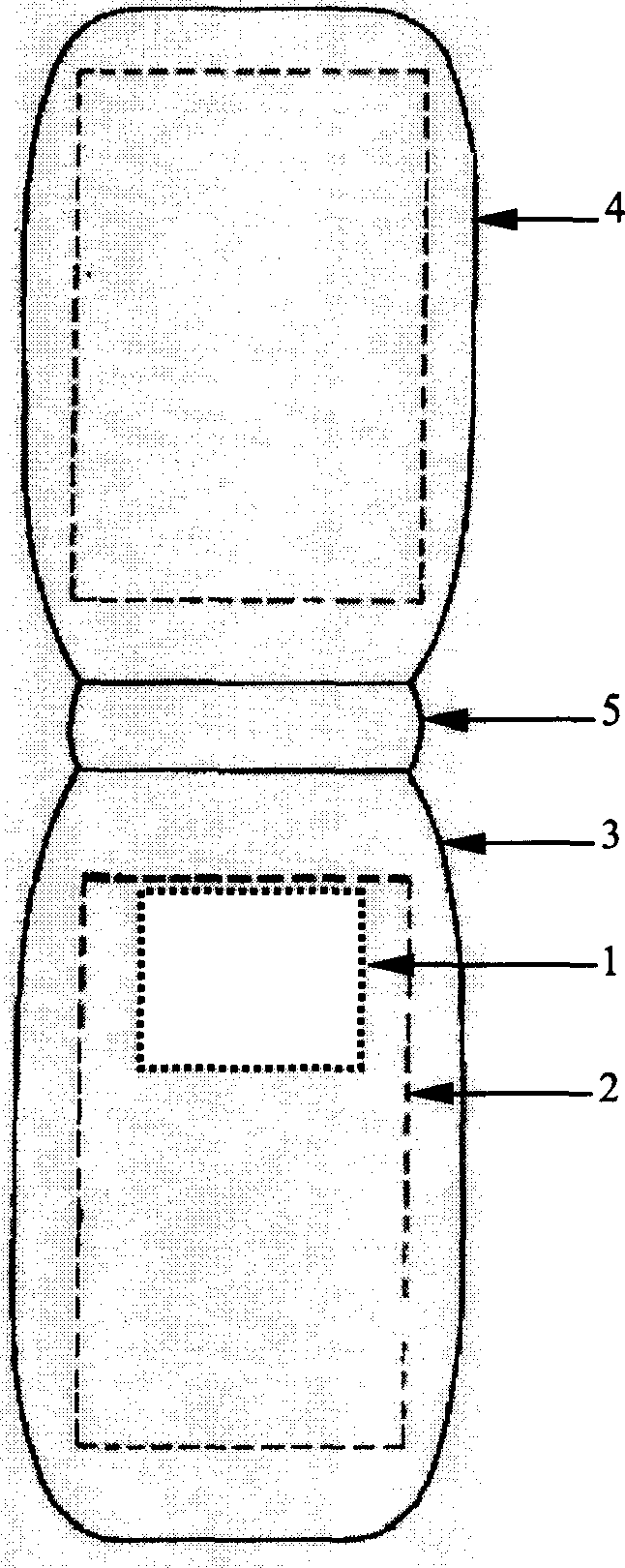
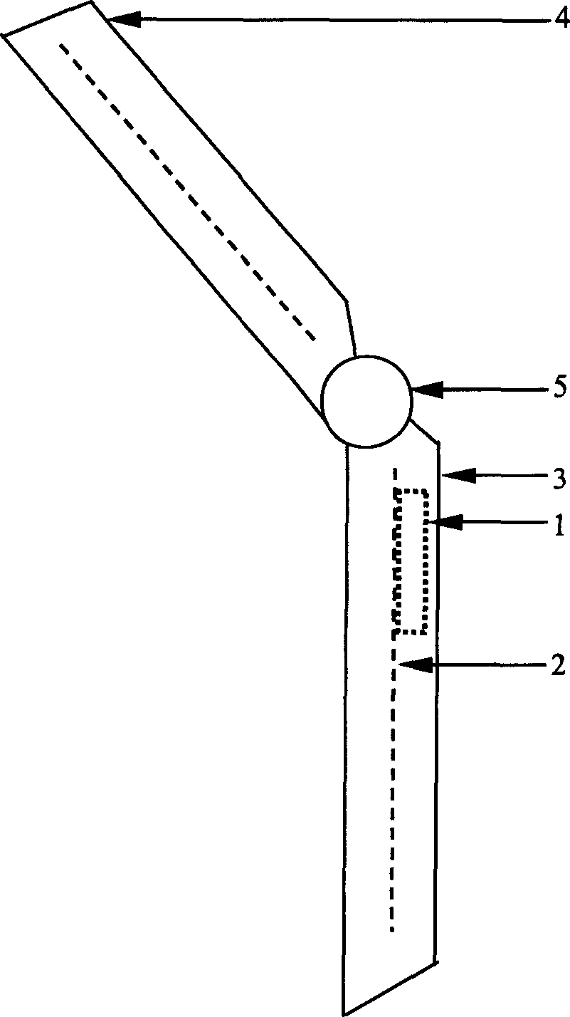
[0066] figure 1 It is a top view of the layout of the terminal diversity antenna provided as the first embodiment of the present invention, which has an antenna unit and an orthogonal feeding device, figure 2 is the side view of this embodiment, where 1 is the antenna unit, 2 is the antenna ground corresponding to antenna unit 1, 3 is the body of the wireless communication terminal, 4 is the flip cover of the wireless communication terminal, and 5 is the gap between the body and the flip cover. Hinge (or shaft).

[0067] The antenna unit 1 in this embodiment adopts such as Figure 7 The microstrip patch antenna shown, at this time, the microstrip 101 and the microstrip 102 fed by orthogonality are respectively connected to their corresponding transmitters (for the transmitting antenna device) or corresponding receivers (for the receiving antenna device). Its far-field pattern un...

Embodiment 2

[0069] Embodiment 2: Diversity antenna with two substantially orthogonal antenna elements positioned between the panel back and the chassis of the terminal body

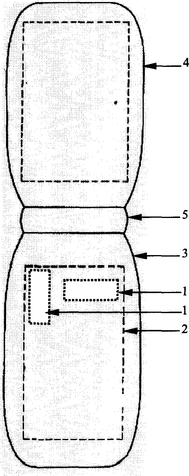
[0070] image 3 It is a top view of the layout of the terminal diversity antenna as the second embodiment of the present invention, which has two substantially orthogonal antenna elements arranged between the panel back of the terminal body and the casing, Figure 4 is the side view of the diversity antenna, where 1 is the antenna unit, 2 is the antenna ground corresponding to antenna unit 1, 3 is the body of the wireless communication terminal, 4 is the flip cover of the wireless communication terminal, and 5 is the gap between the body and the flip cover. Hinge (or shaft).

[0071] The antenna unit 1 in this embodiment adopts such as Figure 8 and Figure 9 In the planar inverted-F antenna shown, the antenna unit 1 is connected to the antenna ground 2 through a metal sheet 202 , and the antenna unit 1 is fed by ...

Embodiment 3

[0074] Embodiment 3: Terminal Diversity Antenna with Two Antenna Units Arranged Between the Panel Back of the Terminal Body and the Cabinet and Between the Screen Back of the Flip Cover and the Cabinet

[0075] Figure 5It is a top view of the layout of the terminal diversity antenna as the third embodiment of the present invention, which has two antenna units arranged between the panel back of the terminal body and the casing and between the screen back of the flip cover and the casing , Image 6 is the side view of the diversity antenna, where 1 is the antenna unit, 2 is the antenna ground corresponding to antenna unit 1, 3 is the body of the wireless communication terminal, 4 is the flip cover of the wireless communication terminal, and 5 is the gap between the body and the flip cover. Hinge (or shaft).

[0076] The antenna unit 1 in this embodiment adopts such as Figure 8 and Figure 9 In the planar inverted-F antenna shown, the antenna unit 1 is connected to the ante...


PUM


Abstract

The disclosed antenna assembly is composed of N pieces (N is larger than or equal to 1) of antenna unit and M pieces (M is larger than or equal to 1) of ground of antenna. K pieces (K larger than zero and smaller than N) of antenna unit are positioned on the ground of antenna between main body and case of wireless communication terminal. Other (N-K) pieces of antenna unit are positioned on the ground of antenna between back of screen of turnable cover and case of wireless communication terminal. Through feeder apparatus, N pieces of antenna unit are connected to relevant transmitter or receiver. Features are: low spatial correlation, no radiation injury, low cost and easy of manufacturing. The invention can be widely applied for wireless communication for obtaining space diversity, angle diversity or polarization diversity of radio wave propagation, or in use for transmitting or receiving time-space coding or multiple inputs and outputs wireless communication system.

Description

technical field [0001] The invention belongs to the technical field of wireless communication diversity antennas, in particular to the wireless communication terminal diversity antenna technology. Background technique [0002] With the rapid development of wireless communication, the number of users is increasing day by day, and the data service is growing continuously. The wireless communication system of single-antenna transceiver is facing severe capacity bottleneck test. It is necessary to further improve the capacity and quality of the current wireless communication system, and seek new Technical solutions. Multiple transmission and multiple reception (MIMO) technology is a new wireless communication technology that utilizes multiple transmitting and multiple receiving antennas. Its transmitted data stream is separated into multiple sub-data streams, which are transmitted simultaneously at the same frequency through different antennas after modulation. Through the scat...

Claims


Application Information

Patent Timeline
IPC IPC(8): H04B7/04H01Q1/24H01Q13/08
Inventor 李忻聂在平
Owner UNIV OF ELECTRONIC SCI & TECH OF CHINA
Why Eureka
Try Eureka