Circuit board automatic drilling machine

A drilling machine and circuit board technology, applied in the direction of boring/drilling, drilling/drilling equipment, metal processing equipment, etc., can solve the problem of unbearable high-priced drilling equipment, inaccurate manual positioning, and the efficiency of drilling low cost, low cost, simple structure and fast drilling speed

Inactive Publication Date: 2006-02-08
HUNAN CREATE SCI & TECH
View PDF0 Cites 23 Cited by
  • Summary
  • Abstract
  • Description
  • Claims
  • Application Information

AI Technical Summary

Problems solved by technology

[0002] At present, professional circuit board manufacturers use large-scale CNC processing equipment to drill circuit boards. This large-scale drilling equipment is basically imported equipment, and the price is as high as hundreds of thousands. Universities and general electronic product R&D and production enterprises and scientific research institutes cannot bear the high price. Drilling equipment; At present, domestic universities, electronic-related product research and development companies, and scientific research institutes are using a large number of methods such as thermal transfer printing and exposure board manufacturing to make PCB prototypes and small batch production. This method solves the problem in professional circuit board manufacturing. The cost of making prototypes in the board factory is high and the cycle is long. However, since the thermal transfer equipment and the exposure board making equipment can only complete part of the work of the rapid board making, the circuit board drilling is a very important task in the rapid board making process. , but due to the high price of existing large-scale CNC drilling equipment, colleges and scientific research enterprises have adopted cheap manual micro-drills to drill holes, but manual micro-drills have several obvious defects: manual positioning is not accurate, The efficiency of drilling is extremely low and the drill bit is easy to break. Therefore, how to achieve low-cost, high-efficiency, and high-precision drilling has become a bottleneck problem for rapid board manufacturing

Method used


Image

  • Circuit board automatic drilling machine
  • Circuit board automatic drilling machine
  • Circuit board automatic drilling machine

Examples


Embodiment Construction

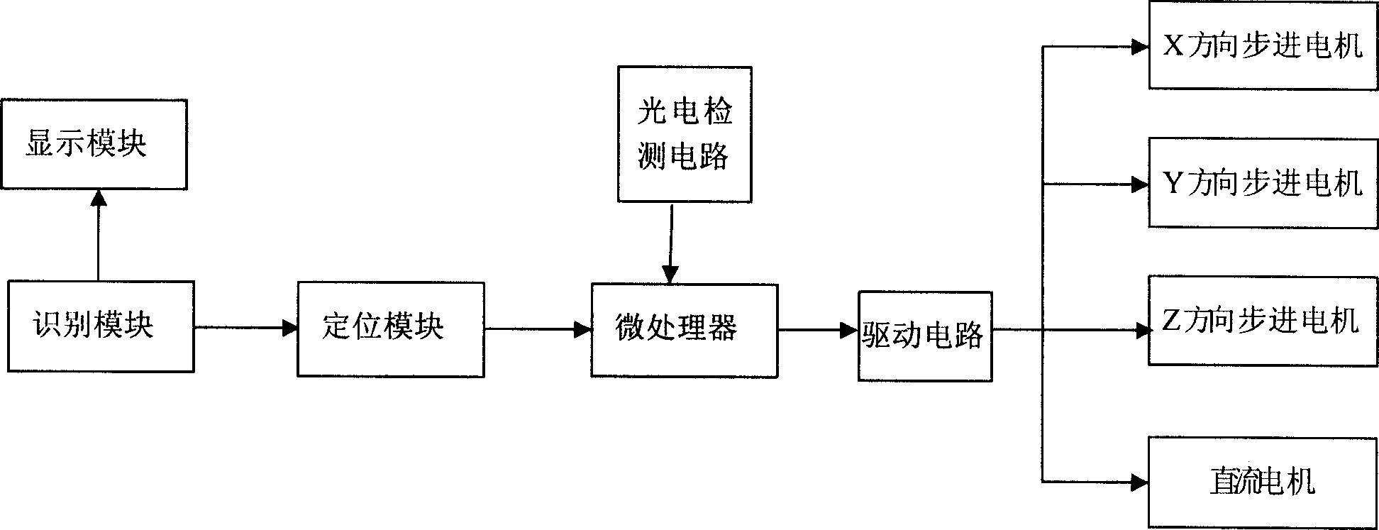
[0012] Such as figure 1 as shown, figure 1 It is a structural diagram of the control part of the present invention, the identification module is connected with the display module, the storage module, and the positioning module respectively, and the identification module reads and identifies the PCB file, on the one hand, obtains and processes the PCB file circuit and drilling data, and processes the processed circuit and the drilling data are displayed by the display module; on the other hand, the data related to the hole is obtained from the PCB file and sent to the positioning module. The positioning module processes the relevant data of the hole, obtains the drilling data of the hole, and sends it to the micro The processor and the microprocessor respectively control the driving circuit according to the drilling data of the hole, and drive the DC motor, the x-axis stepping motor, and the z-axis stepping motor to complete the drilling work. The photoelectric detection circu...


PUM


Abstract

The invention discloses a circuit board automated drilling machine, which comprises foundation, operating platform, x-direction motion mechanism, bidimensional motion mechanism, y-direction motion mechanism, continuous current dynamo, drill, recognition mould, display mould, locating mould, microprocessor and driving circuit. The invention has the following settings: operating platform locating on y-direction; the upper of operating platform locating x-direction motion mechanism, bidimensional motion mechanism, continuous current dynamo and drill fixed on foundation; recognition connecting with display mould, storage mould and locating mould and recognizing drill data in PCB document; locating mould processing drill hole data and sending it to microprocessor; and microprocessor controlling drive circuit and driving x-direction motion mechanism, bidimensional motion mechanism, y-direction motion mechanism and continuous current dynamo to complete drilling. The invention has the advantages of simple structure, low cost, small bulk, accurate drilling and stably operating.

Description

technical field [0001] The invention relates to a drilling device, in particular to an automatic circuit board drilling machine. Background technique [0002] At present, professional circuit board manufacturers use large-scale CNC processing equipment to drill circuit boards. This large-scale drilling equipment is basically imported equipment, and the price is as high as hundreds of thousands. Universities and general electronic product R&D and production enterprises and scientific research institutes cannot bear the high price. Drilling equipment; At present, domestic universities, electronic-related product research and development companies, and scientific research institutes are using a large number of methods such as thermal transfer printing and exposure board manufacturing to make PCB prototypes and small batch production. This method solves the problem in professional circuit board manufacturing. The cost of making prototypes in the board factory is high and the cyc...

Claims


Application Information

Patent Timeline
Patent Type & Authority Applications(China)
IPC IPC(8): B23B39/16
Inventor 张宏立
Owner HUNAN CREATE SCI & TECH
Why Eureka
Try Eureka