Permanent magnet biased external rotor radial magnetic bearing

A technology of permanent magnetic bias and external rotor, applied in bearings, shafts and bearings, shafts, etc., can solve the problems of large excitation current, increased bearing power consumption, long axial length, etc., to reduce the loss of control power amplifier, reduce Volume, easy to control effect

Inactive Publication Date: 2006-02-08
BEIHANG UNIV
View PDF0 Cites 19 Cited by
  • Summary
  • Abstract
  • Description
  • Claims
  • Application Information

AI Technical Summary

Problems solved by technology

However, some of the current permanent magnet bias outer rotor radial magnetic bearing structures are based on ordinary radial electromagnetic bearings, and permanent magnets are placed upward on the electromagnetic magnetic circuit, so that the magnetic flux generated by the control coil must pass through the permanent magnets. Due to the large reluctance of the permanent magnet, a large excitation current is required for the control coil to generate a certain electromagnetic flux, which will obviously increase the power consumption of the bearing; some structures directly connect the permanent magnet to the stator laminated core, so that the permanent magnet When the magnetic circuit passes through the stator core vertically, it will lose too much magnetomotive force, which will greatly weaken the attraction force of the permanent magnet to the rotor shaft; there are also some structures that connect the permanent magnet with the laminated core through the magnetic ring, and the electric excitation The magnetic circuit forms a loop through the laminated iron core, so that the permanent magnetomotive force will not be lost in the laminated iron core, and the electric excitation magnetic circuit will not pass through the permanent magnet itself, but the radial magnetic bearing of this structure has a permanent The plane where the magnetic magnetic circuit is located and the plane where the electric excitation magnetic circuit is located are perpendicular to each other, which will result in a longer axial length, so it cannot meet the small size and light weight requirements of spacecraft such as satellites and space stations. The existing permanent magnet bias If the radial magnetic bearing is installed, the bias magnetic field generated by the permanent magnet is coupled in the X and Y directions, that is to say, the permanent magnet itself (whether it is a whole ring or a single permanent magnet) generates a bias magnetic field in the X direction, At the same time, a bias magnetic field is generated in the Y direction, so if the rotor is disturbed in the X direction, not only the bias magnetic field in the X direction will change, but also the bias magnetic field in the Y direction will also change, so Greatly increased the difficulty of control

Method used


Image

  • Permanent magnet biased external rotor radial magnetic bearing

Examples


Embodiment Construction

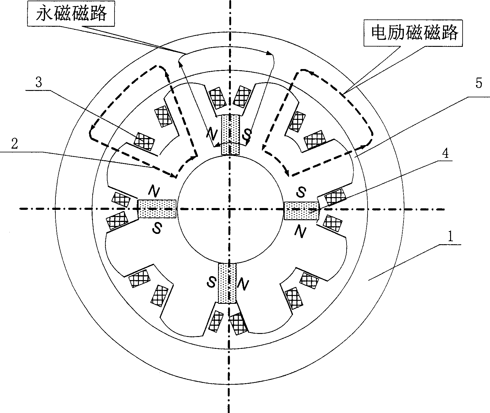
[0008] Such as figure 1 As shown, it is the coil low power consumption permanent magnet bias outer rotor radial magnetic bearing of the technical solution of the present invention, which is composed of rotor core 1, permanent magnet 4, stator core 2, and excitation coil 3, and the magnetic poles of the 8 stator cores are all Distributed on the circumference, surrounded by an excitation coil 3, four permanent magnets 4 are embedded in the stator core 2, and placed along the +X, -X, +Y and -Y directions, wherein along the +X, -X directions The placed permanent magnet 4 generates a bias magnetic field in the X direction, and the permanent magnet 4 placed along the +Y and -Y directions generates a bias magnetic field in the Y direction. There is a certain gap between the outer surface of the stator core 2 and the inner surface of the rotor core 1. The gap forms an air gap 5 (generally 0.3mm). In specific applications, the permanent magnet bias outer rotor radial magnetic bearings...


PUM


Abstract

The permanent magnetic offset external rotor magnetic radial bearing features that it consists of rotor iron core, permanent magnet, stator iron core and exciting winding. Eight stator iron core magnetic poles distributed homogeneously in a circumference are wound with exciting winding; and four permanent magnets are embedded inside the stator iron core separately in the +X, -X, +Y and -Y directions to produce offset magnetic field in X direction and offset magnetic field in Y direction separately. Between the outer surface of the stator iron core and the inner surface of the rotor iron core, there is air gap. The permanent magnetic offset external rotor magnetic radial bearing of the present invention has the advantages of no coupling between the X direction permanent magnetic path and the Y direction permanent magnetic path, small size, low power consumption, reliable performance and easy control.

Description

Technical field [0001] The invention relates to a non-contact magnetic suspension bearing, in particular to a low-power consumption, small-volume permanent magnet bias external rotor radial magnetic bearing, which can be used as non-contact support for rotating parts in spacecraft such as satellites and space stations. Background technique [0002] Magnetic suspension bearings are divided into pure electromagnetic bearings and hybrid magnetic suspension bearings with permanent magnetic bias and electromagnetic control. The former uses large current and consumes a lot of power, and the hybrid magnetic suspension bearings with permanent magnetic bias and electromagnetic control. The magnetic field generated by the permanent magnet bears the main load. Bearing capacity, the electromagnetic field provides auxiliary adjustment bearing capacity, so this kind of bearing can greatly reduce the control current and reduce the loss. However, some of the current permanent magnet bias ou...

Claims


Application Information

Patent Timeline
Patent Type & Authority Applications(China)
IPC IPC(8): F16C32/04
CPCF16C32/0465F16C2300/20
Inventor 孙津济房建成韩邦成
Owner BEIHANG UNIV
Why Eureka
Try Eureka