

In-position gas analyzing system with in-position calibrating function
A gas analysis system and function technology, which is applied in the direction of analyzing materials, material analysis by optical means, measuring devices, etc., can solve the problems of complex devices, difficult installation and debugging, and high requirements for processing and installation accuracy, and achieves simple device and calibration. Reliable results and low assembly accuracy requirements
- Summary
- Abstract
- Description
- Claims
- Application Information
AI Technical Summary
Problems solved by technology
Method used
Image

Examples
Embodiment 1
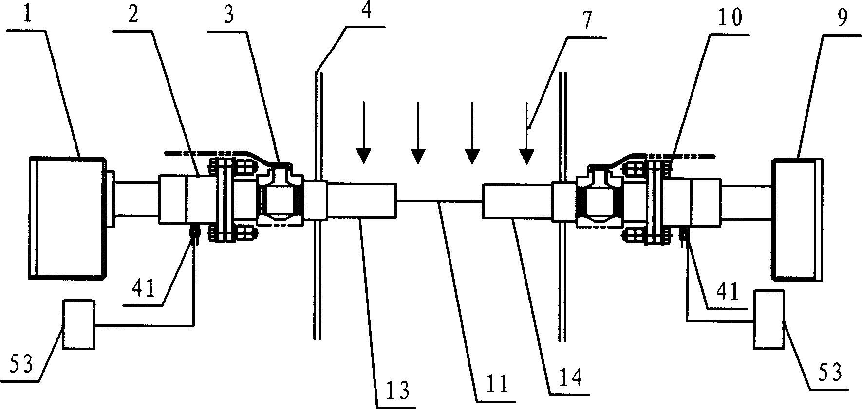
[0035] Such as figure 2 , Figure 7 As shown, the on-site gas analysis system is a non-dispersive infrared spectroscopy (NDIR) gas analysis system. The light emitting device 1 and the light receiving device 9 are connected to the measured process gas pipeline 4 through a mechanical connection structure, including a flange matching body 2 and a valve 3 . The optical path between the light-emitting device 1 and the light-receiving device 9 can be adjusted by adjusting the bolt 10 on the mechanical connection structure to squeeze the O-ring in the middle of the flange mating body 2 .
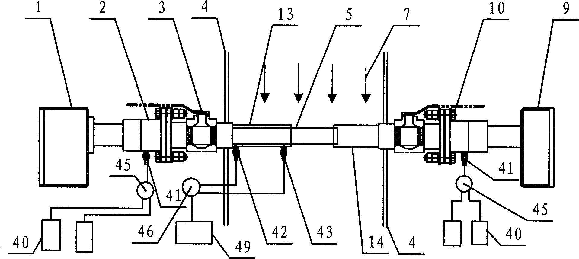
[0036] The additional tube, that is, the telescopic tube 5 is installed inside the first inner tube 13 connected with the mechanical connection structure, and the telescopic tube 5 is pneumatically driven. The cross section of the telescopic tube is circular, and this structure is easy to process and install. The control device is: the detachable end block 52 is installed on the inner wall of th...
Embodiment 2
[0039] Such as figure 2 , Figure 7 As shown, the measuring tube is the first extension tube 13 and the second extension tube 14 with a mechanical connection structure on both sides of the measured gas pipeline; the additional tube is the telescopic tube 5 installed in the first extension tube, and the telescopic tube 5 is slidably sleeved on the first extension tube 13, and the protruding end of the telescopic tube 5 cooperates with the second extension tube 14; the control device is used to control the telescopic tube to extend into the second extension tube or retract into Drive for the first extension tube.
[0040] All the other structures and working processes of this embodiment are the same as those of Embodiment 1.
Embodiment 3
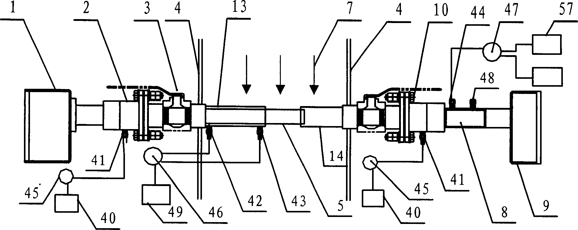
[0042] Such as image 3 , Figure 7 As shown, the on-site analysis system with on-site calibration function described in Embodiment 1 is provided with a gas chamber 8 near the light receiving device 9, and there are ventilation joints 44, 48 on the chamber, and a calibration gas source 57 (including Zero gas and standard gas) are connected through the valve 47 and the ventilation joint 44.
[0043] The working process is as follows: during measurement, control the telescopic tube 5 to retract into the inner cylinder 13 on the side of the light emitting device, and fill the internal aperture of the mechanical connection structure and the inner cylinder 13, 14 through the ventilation joint 41 with a pressure higher than the internal pressure of the process gas pipeline to be measured. Powerful zero gas protects the optical window from contamination and ensures the accuracy of the optical path measurement; the valve 47 is used to control the filling of zero gas into the chamber ...
PUM
 Abstract
Description
Claims
Application Information