
Lighting optical device

A technology of optical device and light source, which is applied in the direction of exposure device, optics, projection device, etc. of photo-plate making process, can solve the problems that it is difficult to exert the maximum performance of DMD, and can not improve the resolution and contrast of the device, so as to achieve the improvement of resolution and contrast, high Resolution, the effect of increasing resolution

Inactive Publication Date: 2006-03-01
RINSOKEN
View PDF4 Cites 9 Cited by
  • Summary
  • Abstract
  • Description
  • Claims
  • Application Information

AI Technical Summary

Problems solved by technology

If the technical measures for illuminating light are insufficient, even if the post-level optical system that processes the exit light of the DMD adopts a high-performance imaging system or projection system, the resolution and contrast of the entire device cannot be improved.
In short, it is difficult to exert the maximum performance of DMD in the traditional lighting method

Method used


Image

  • Lighting optical device
  • Lighting optical device
  • Lighting optical device

Examples


Embodiment 1

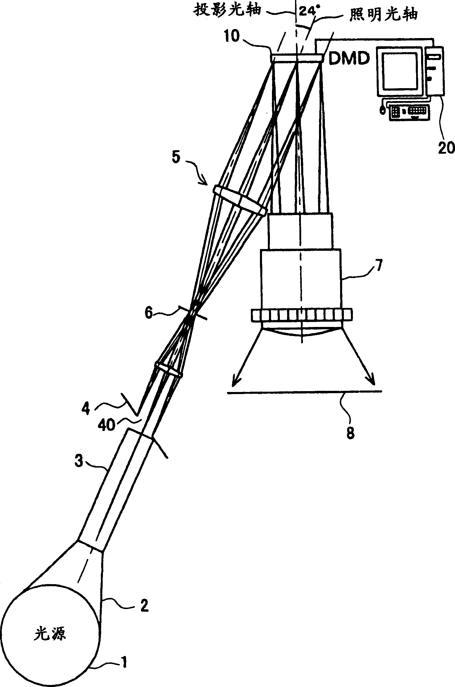
[0037] figure 2 A projector utilizing the illumination optics of the present invention is shown. The projector is provided with an illumination optical system and a projection optical system via the DMD. The optical axis of the projection optical system is perpendicular to the DMD, and the optical axis of the illumination optical system crosses at an angle of 24 degrees at the position of the DMD. This angle is 24 degrees in this embodiment, but sometimes it is 20 degrees depending on the DMD used.

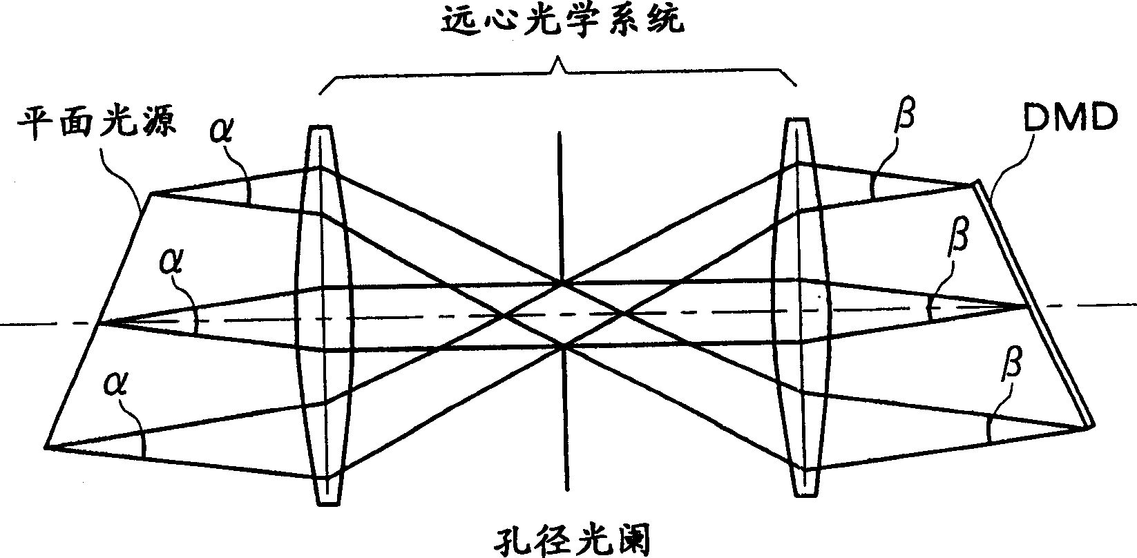
[0038]The illumination optical system is composed of a light source 1 , a light collecting device 2 , a rod integrator 3 , a field stop 4 , telecentric lens groups 5 on both sides and an aperture stop 6 .

[0039] The DMD 10 side of the projection optical system consists of a telecentric projection lens 7 and a display screen 8 .

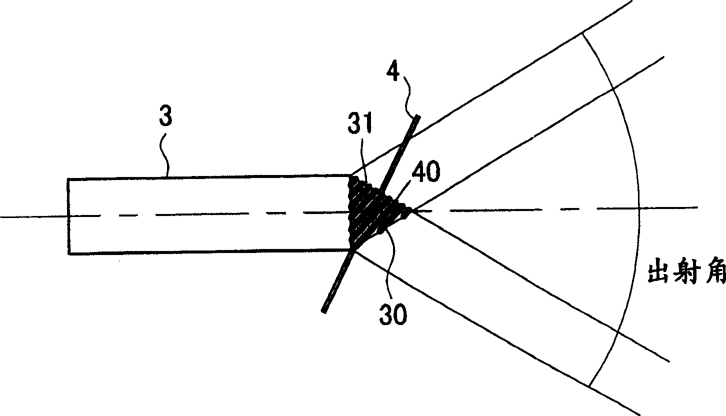
[0040] The rod integrator 3 guides the light emitted from the light source and adjusts the illuminance to be uniform. The field stop 4 is provided...

Embodiment 2

[0047] Figure 4 An exposure apparatus utilizing the illumination optical apparatus of the present invention is shown. The exposure device is provided with an illumination optical system and a bilateral telecentric reduction projection optical system via the DMD10 connected to the computer 20 , and the pattern previously stored in the computer 20 is displayed on the DMD10 , and the pattern is exposed on the sample 30 .

[0048] The illumination optical device constituting the illumination optical system is composed of a light source 1 , a light collecting device 2 , a rod integrator 3 , a lens group 5 constituting a telecentric optical system, and an aperture stop 6 .

[0049] The exit end surface 31 of the rod integrator 3 is obliquely cut at an angle B, and the axis of the rod integrator 3 is skewed at an angle A from the illumination optical axis. The exit end face 31 of the rod integrator 3 and the DMD 10 satisfy the Simpfruge relation for a telecentric optical system.

...


PUM


Abstract

To provide a lighting optical system of a spatial optical modulator comprising an array of micromirrors whose resolution and contrast are high. A plane light source installed obliquely to an optical axis and a telecentric optical system are installed, the plane light source and spatial optical modulator are arranged so as to satisfy shineproof relationship, and lighting is performed by imaging the plane light sources so that a main light beam is aligned with the optical axis of lighting on all the micromirrors on the spatial optical modulator installed obliquely at a specified angle to the optical axis of lighting. Consequently, the main light beam of illumination light lighting up the individual micromirrors of the spatial optical modulator is parallel and lights up the spatial optical modulator obliquely at the specified angle. Consequently, the high resolution and the high contrast excluding stray light are obtained.

Description

technical field [0001] A spatial light modulator composed of an array of micromirrors represented by a digital micromirror device (Digital Micro Mirror Device) (hereinafter referred to as DMD), used as a pattern for an image display device such as a projector, a light shaping device or an exposure device, etc. Generating components, as well as the confocal scanning components of the microscope are utilized. A device using a spatial light modulator is composed of a spatial light modulator body and two optical systems, the front stage and the rear stage. Firstly, light is introduced into the spatial light modulator by the illumination optical system of the previous stage, the spatial light modulation is performed in the spatial light modulator, and the output light has Desired functions corresponding to the purpose of the device utilizing the spatial light modulator. The present invention relates to an illumination optical device comprising an illumination optical system of a ...

Claims


Application Information

Patent Timeline
IPC IPC(8): G02B26/08G02B27/18G02F1/13G03F7/20H04N5/74G02B19/00G03B21/00G03B21/14H01L21/027
Inventor 林彻
Owner RINSOKEN
Features
  • Generate Ideas
  • Intellectual Property
  • Life Sciences
  • Materials
  • Tech Scout
  • Unparalleled Data Quality
  • Higher Quality Content
  • 60% Fewer Hallucinations
Learn More