Integrated block type valve-block hydraulic control system for drilling machine

A hydraulic control system and integrated block technology, which is applied to the automatic control system of drilling, drilling equipment, earthwork drilling and production, etc., can solve the problems of cumbersome connection, troublesome operation, easy heating, etc., and achieve easy maintenance, reduced energy consumption, and easy operation. simple effect

Inactive Publication Date: 2006-03-08
武汉世纪金道石油技术开发有限公司 +1
View PDF0 Cites 1 Cited by
  • Summary
  • Abstract
  • Description
  • Claims
  • Application Information

AI Technical Summary

Problems solved by technology

However, the single-row hydraulic system is prone to heat, high energy consumption, cumbersome connection...

Method used


Image

  • Integrated block type valve-block hydraulic control system for drilling machine
  • Integrated block type valve-block hydraulic control system for drilling machine
  • Integrated block type valve-block hydraulic control system for drilling machine

Examples


Embodiment Construction

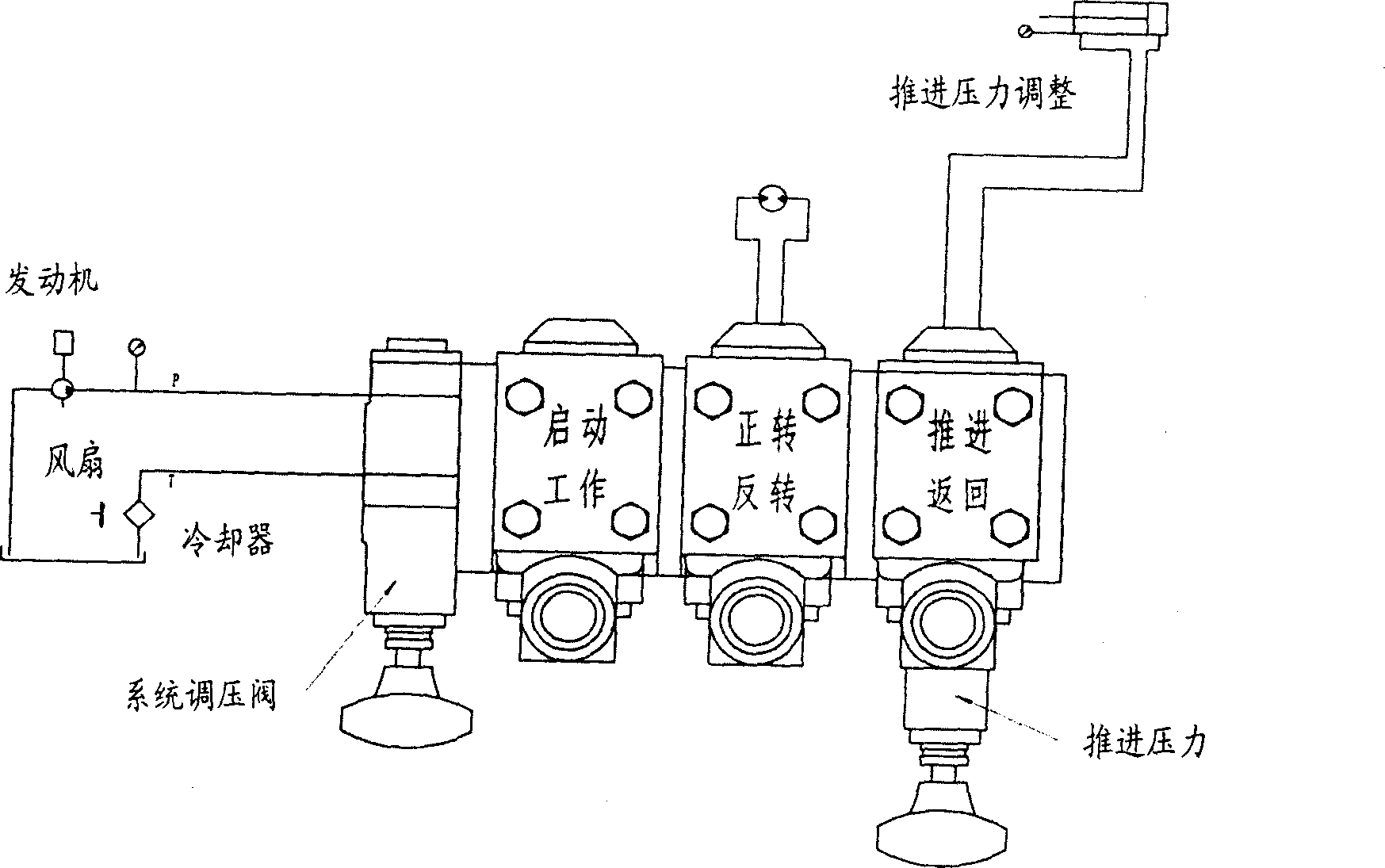
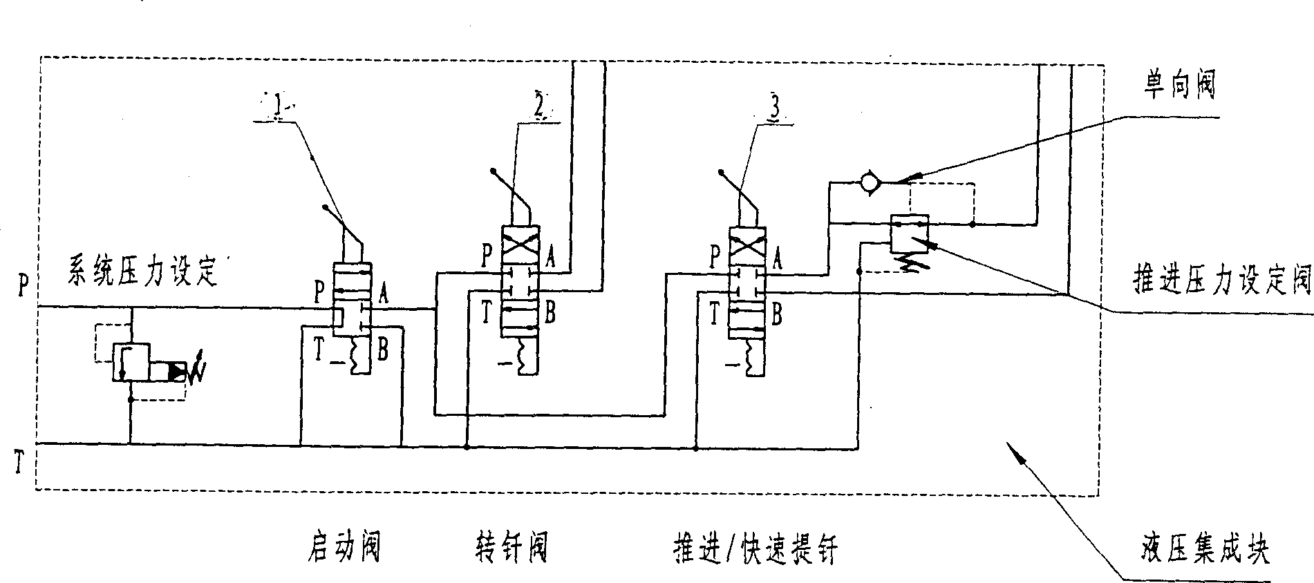
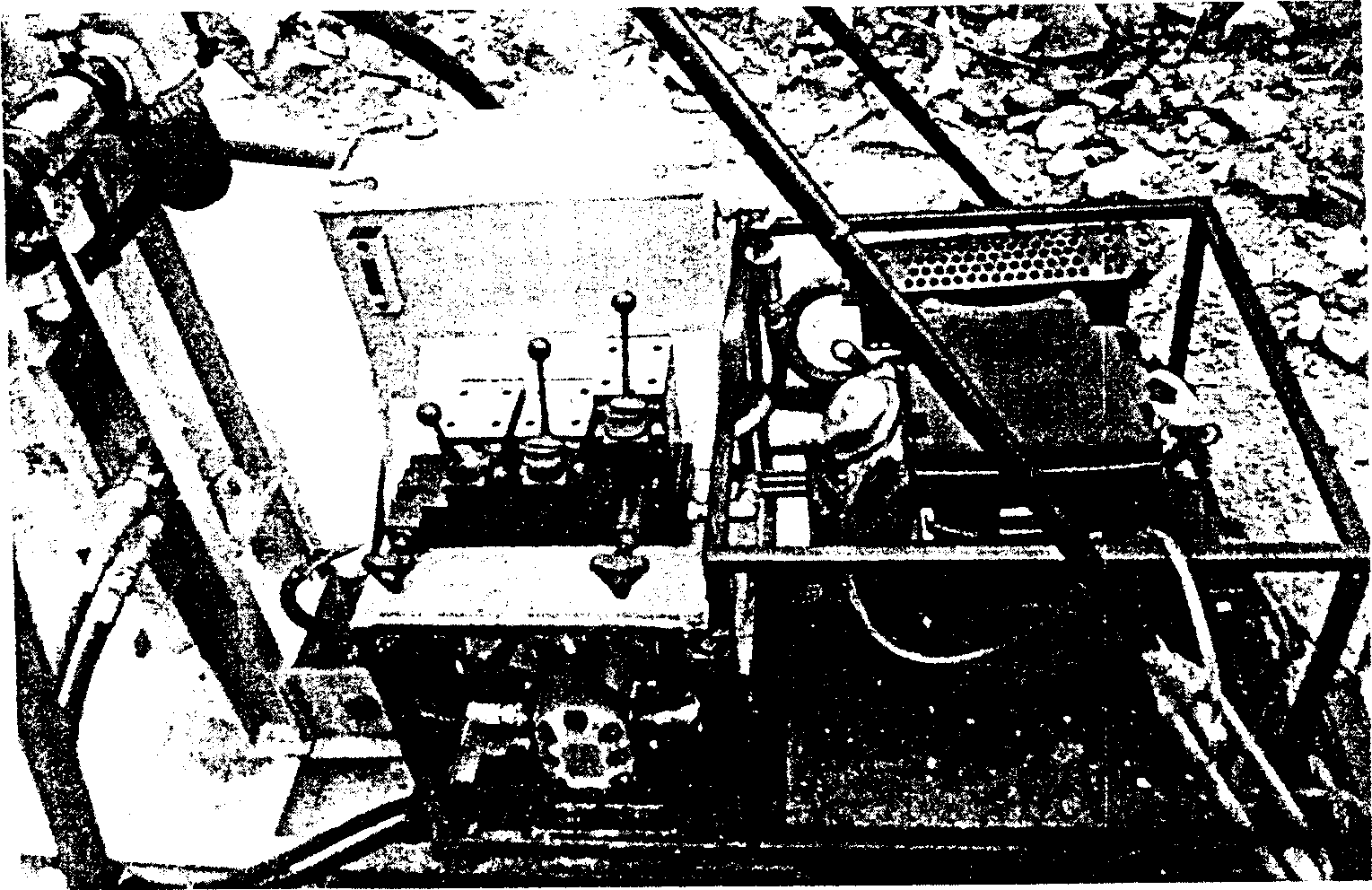
[0010] The structure of the multi-functional full hydraulic mountain drilling rig is mainly composed of two parts: the drill frame and the hydraulic power station. The drill frame part mainly includes the drill frame base, the impactor, and the reducer. The motor, the hydraulic motor, is connected to the hydraulic power unit, the reducer is connected to the thruster through the splint and the slide plate, the impactor is connected to the reducer through the connecting flange, the hydraulic power unit is installed on the drill frame through the pin shaft, and the hydraulic power unit is installed on the drill frame. Lever to control the impactor. Drilling rig control with integrated block hydraulic control system such as figure 1 As shown, the valves that control the action of the drilling machine are assembled on the manifold, and the manifold is directly connected to the actuators of the drilling machine, so that the entire system has only six pipelines, which reduces the num...


PUM


Abstract

A integrated block type valve block hydraulic control system for drill machine, which features the valve for controlling drill machine is integrated in a block whose valves have holes for oil flowing by being connected pipe with hydraulic power pump, the integrated block connected with hydraulic motor through pipe and oil cylinder in slide frame by check valve, the piston stem driving slide board and speed reducer to up/down reciprocating motion in slide frame. Said invention integrates the drilling and chiseling movement control into a controller which can complete the zero pressure starting, positive and negative rotation for drilling and dismounting drill stem, lifting drill stem by utilizing integrated valve set and reasonable hydraulic control system to reduce default rate.

Description

technical field [0001] The invention relates to an integrated block type valve block hydraulic control system for drilling rigs. technical background [0002] The current drilling rig generally adopts a single-row split hydraulic control system to drive and control the various actions of the drilling rig. The main engine of the drilling rig is powered by a hydraulic oil pump, which converts mechanical energy into liquid pressure energy. The high-pressure fluid output by the oil pump drives the actuators (hydraulic motor and hydraulic pressure) Oil cylinder) converts the hydraulic pressure energy into mechanical energy, so as to realize the rotation, pressurization and rapid lifting of the drilling rig. However, the single-row hydraulic system is prone to heat, high energy consumption, cumbersome connections, high noise, and the reversing valve is a manual proportional multi-way valve, which is troublesome to operate. Contents...

Claims


Application Information

Patent Timeline
IPC IPC(8): F15B13/02E21B44/00
Inventor 李恒舒李东安张仲桥向龙斌李砚耕
Owner 武汉世纪金道石油技术开发有限公司
Why Eureka
Try Eureka