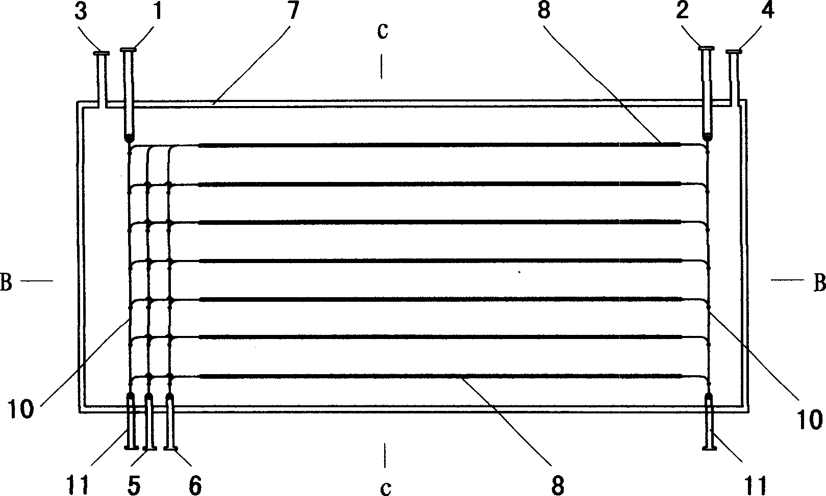
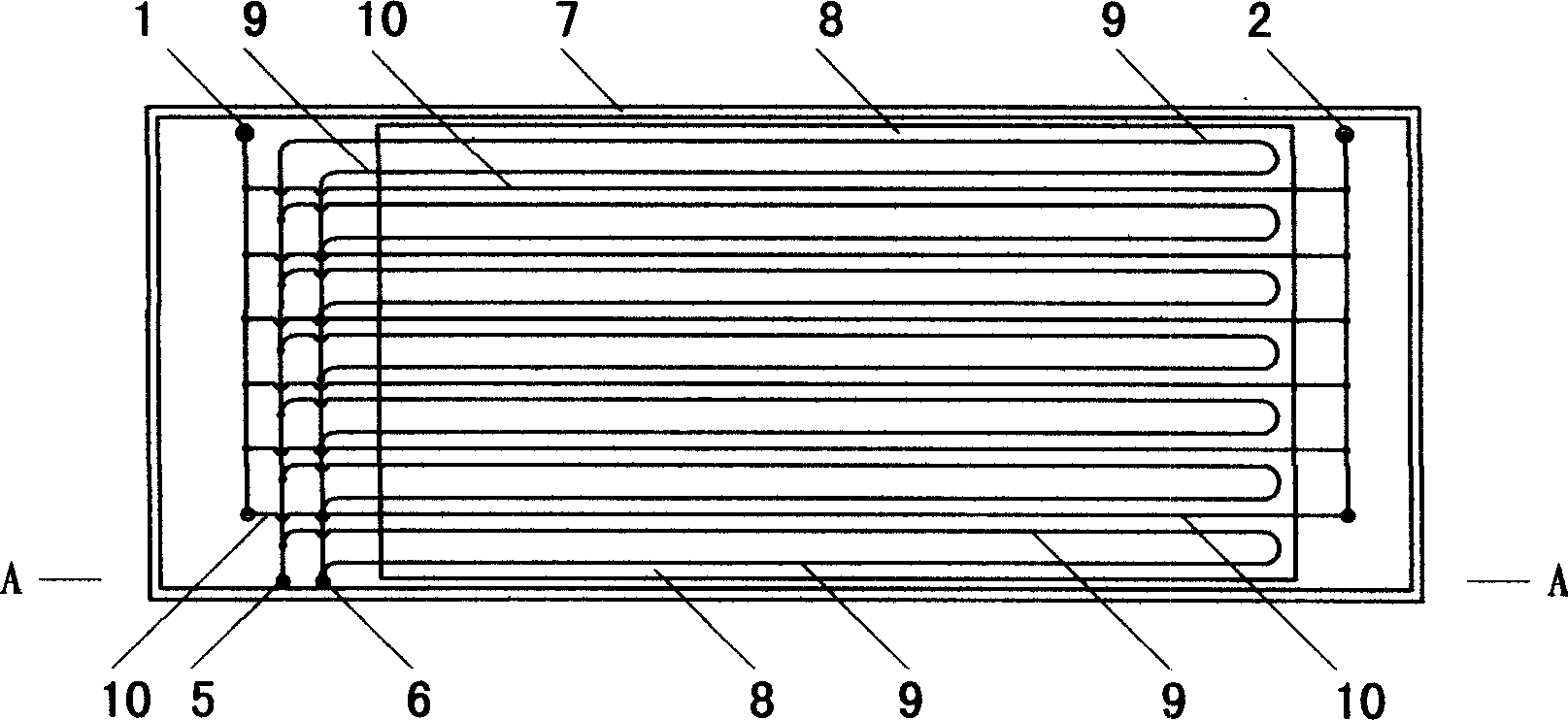
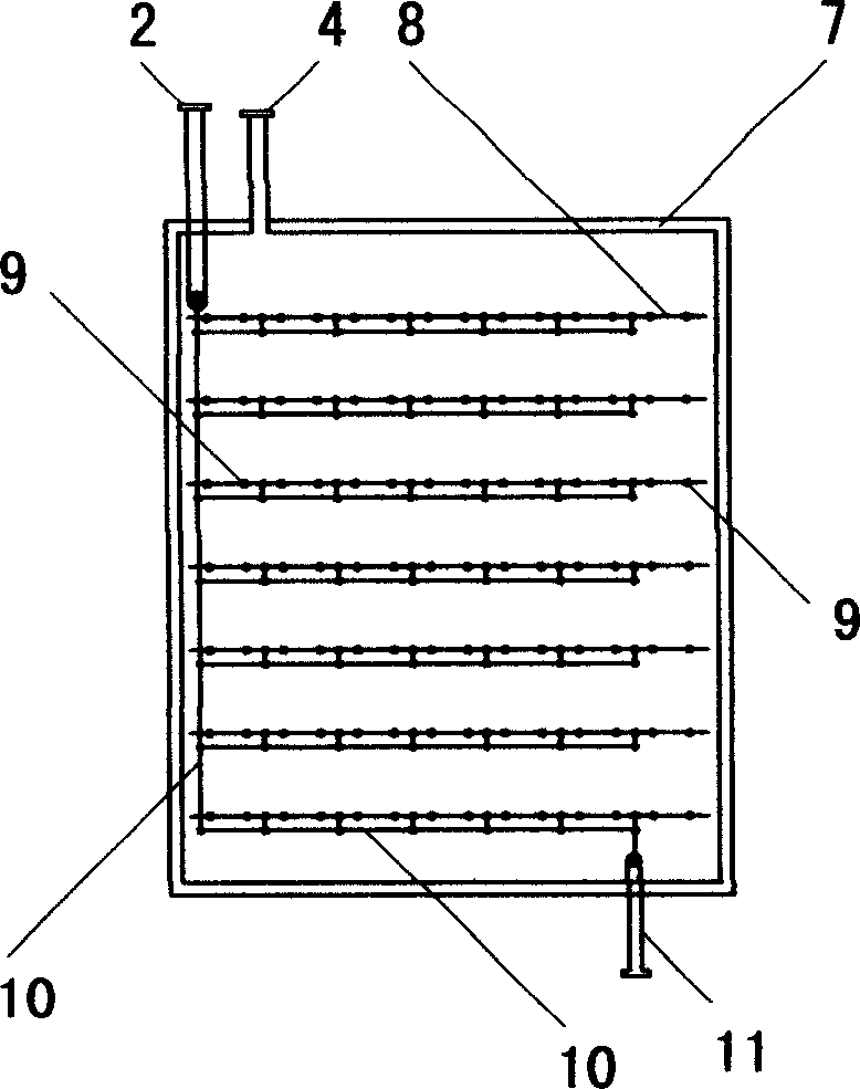
Plate indirect ice-melting and direct ice-melting concurrent ice-storage tank

An ice storage tank and ice melting technology, which is applied in the directions of space heating and ventilation, heating mode, lighting and heating equipment, etc. Heat loss and other problems, to achieve the effect of uniform freezing and melting, reducing scale, and low cooling rate

Inactive Publication Date: 2006-03-08
林智忠
View PDF0 Cites 3 Cited by
  • Summary
  • Abstract
  • Description
  • Claims
  • Application Information

AI Technical Summary

Problems solved by technology

The working principles of the existing ice plates, ice balls and inner ice-melting ice cylinders (troughs) are roughly the same. They all use low-temperature brine as the heat transfer medium of the cold storage medium. Outside the cold storage medium, the internal ice-melting refrigerant is in the cold storage medium, and they have common disadvantages: they require a heat exchanger and a large amount of refrigerant, which increases the secondary heat transfer loss; when the ice layer melts, the refrigerant A water layer is formed between the agent and the ice layer, so the thermal resistance is large when the ice is melted and heat exchanged, which affects the cooling rate; the cooling temperature is higher than that of the external ice-melting type, which increases the capacity of the air-conditioning terminal system and increases the investment of the air-conditioning system
In the existing external ice-melting system, the water space in the ice storage tank should account for half, that is, the ice storage rate of the ice storage tank is not more than 50%, so the volume of the ice storage tank is large; the outer surface of the coil is frozen unevenly, and the ice storage It is easy to form non-melting ice layer and ice bridge locally in the tank, so it is necessary to increase the agitator and ice thickness controller to control the freezing state of the ice layer. The agitator and ice thickness controller used in the current technology have a high failure rate; the agitator works When the ice layer is not completely melted, it will bring a large amount of air into the ice storage tank, making the frozen water weakly acidic, increasing the scale of the equipment on the chilled water side of the air conditioner, and accelerating the corrosion of metal components; when the ice layer has not completely melted, heat the remaining ice outside the ice storage coil Low ice storage efficiency

Method used


Image

  • Plate indirect ice-melting and direct ice-melting concurrent ice-storage tank
  • Plate indirect ice-melting and direct ice-melting concurrent ice-storage tank
  • Plate indirect ice-melting and direct ice-melting concurrent ice-storage tank

Examples


specific Embodiment approach 2

[0023] Such as Figure 4 The shown is a plate-type ice storage tank system in which indirect ice melting and direct ice melting coexist, and the indirect ice melting channel drainage type ice storage tank system mainly includes:

[0024] 1) Refrigerant or brine circuit: the outlet of the refrigerator 20 is connected to the ice storage tank 12 with plate-type indirect ice-melting and direct ice-melting through the inlet 6 of the refrigeration coil, and the plate-type ice storage with both indirect ice-melting and direct ice-melting The tank 12 is connected to the refrigerator 20 through the outlet 5 of the refrigeration coil.

[0025] 2) Air-conditioning water circuit: The water outlet of the refrigeration pump 18 is divided into two channels, one of which is connected to the plate-type ice storage tank 12 where indirect ice melting and direct ice melting coexist through the indirect ice melting inlet valve 19, the indirect ice melting coil inlet 1, and then through the The indi...

specific Embodiment approach 3

[0030] Such as Figure 5 The shown is a plate-type indirect ice-melting and direct ice-melting ice-storage tank system implemented by an indirect ice-melting channel brine type ice-storage tank system, which mainly includes:

[0031] 1) Refrigerant or brine circuit: the outlet of the refrigerator 20 is connected to the ice storage tank 12 with plate-type indirect ice-melting and direct ice-melting through the inlet 6 of the refrigeration coil, and the plate-type ice storage with both indirect ice-melting and direct ice-melting The tank 12 is connected to the refrigerator 20 through the outlet 5 of the refrigeration coil.

[0032] 2) The refrigerant circuit of the indirect ice-melting channel of the air conditioner: the outlet of the refrigeration pump 18 is connected to the ice storage tank 12 of the plate-type indirect ice-melting and direct ice-melting through the inlet 1 of the indirect ice-melting coil, and the plate-type indirect ice-melting and direct ice-melting coexist...

specific Embodiment approach 4

[0037] Such as Figure 6 The shown is a plate-type ice storage tank system in which indirect ice melting and direct ice melting coexist, and the indirect ice melting channel refrigerant heat exchange type ice storage tank system mainly includes:

[0038] 1) Refrigerant or brine circuit: the outlet of the refrigerator 20 is connected to the ice storage tank 12 with plate-type indirect ice-melting and direct ice-melting through the inlet 6 of the refrigeration coil, and the plate-type ice storage with both indirect ice-melting and direct ice-melting The tank 12 is connected to the refrigerator 20 through the outlet 5 of the refrigeration coil.

[0039] 2) Air-conditioning water circuit: The outlet of the refrigeration pump 18 is divided into two circuits, one of which is connected to the water-side inlet of the heat exchanger 17 through the indirect ice-melting inlet valve 19, and the water-side outlet of the heat exchanger 17 is connected to the air-conditioning terminal 13 and...


PUM


Abstract

A board type direct / indirect ice melting combined ice storage trough is disclosed, which contains trough body, heat exchange board, refrigerating coil pipe and indirect ice melting coil pipe. Said invention features the refrigeration coil pipe and indirect ice melting coil pipe distributed on surface of heat exchange board, the inlet-outlet and inner wall of refrigerating coil pipe forming refrigerating path, the inlet-outlet and inner wall of indirect ice melting coil pipe forming indirect ice melting path, the direct ice melting path formed by direct ice melting inlet and outlet, inner wall of trough, outer wall of refrigerating coil pipe and indirect ice melting coil pipe, and surface of heat exchange board.

Description

Technical field: [0001] The invention relates to a cold storage air-conditioning technology, in particular to a plate-type ice storage tank with coexistence of indirect ice melting and direct ice melting for an ice storage air conditioning system in a cold storage air conditioner. Background technique: [0002] The cold storage air-conditioning system is at night when the power grid is at a low point and the price of electricity is relatively cheap. The cooling capacity in the cold storage equipment is released to meet the needs of peak air-conditioning loads or cooling needs of production processes, thereby reducing the load of the power grid during peak hours and realizing the air-conditioning system that "shifts peaks and fills valleys" of power loads. [0003] Ice storage air-conditioning systems are classified according to the form of ice storage, and can be divided into static ice storage systems and dynamic ice storage systems. Dynamic ice storage systems are rarely ...

Claims


Application Information

Patent Timeline
Patent Type & Authority Applications(China)
IPC IPC(8): F24F5/00
Inventor 林智忠
Owner 林智忠
Why Eureka
Try Eureka