Fabrication method of field emitter electrode

An emitter electrode, manufacturing field technology, applied in electrode system manufacturing, discharge tube/lamp manufacturing, cold cathode manufacturing, etc., can solve problems such as low mechanical shock resistance and poor adhesion strength of carbon nanotubes

Inactive Publication Date: 2006-03-22
SAMSUNG ELECTRO MECHANICS CO LTD
View PDF1 Cites 8 Cited by
  • Summary
  • Abstract
  • Description
  • Claims
  • Application Information

AI Technical Summary

Problems solved by technology

[0009] The method of electrophoresis can achieve relatively uniform dispersion of carbon nanotubes and simplify the whole process, but the problem is that the mechanical impact resistance is low due to the poor bonding strength of carbon nanotubes, so this method is required for long service life. is not suitable for the device

Method used


Image

  • Fabrication method of field emitter electrode
  • Fabrication method of field emitter electrode
  • Fabrication method of field emitter electrode

Examples


Embodiment

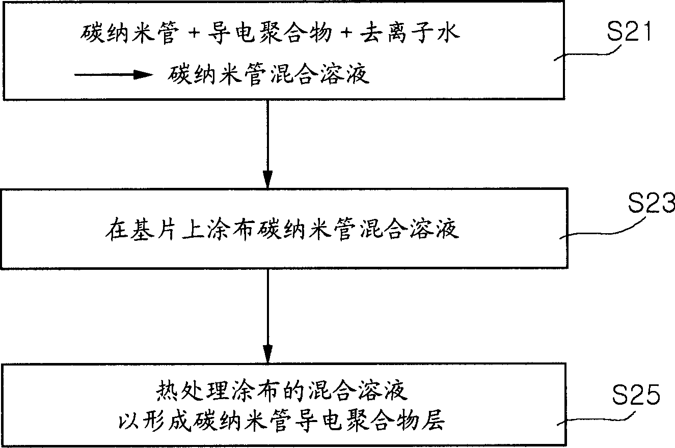
[0036]First, in order to prepare the carbon nanotube mixture according to the present invention, 3 grams of poly(3,4-ethylenedioxythiophene) (Baytron P, Bayer) as a conductive polymer were weighed out, and 15 milligrams (mg) were passed through chemical vapor Multi-walled carbon nanotubes prepared by phase deposition (CVD). The conductive polymer and carbon nanotubes were mixed in 97 grams (g) of deionized water to prepare the desired carbon nanotube mixture. In order to improve the adhesive strength of the substrate, 4 grams of isopropanol, 1.5 grams of ethylene glycol, 1.2 grams of tetraethoxysilane, and 1 gram of acetic acid (100%) were added to the carbon nanotube mixture, and an additional 30 mg was added as A dispersant of benzalkonium chloride (BKC) was added to the CNT mixture. The viscosity of the carbon nanotube mixture was measured to be about 90 cps.

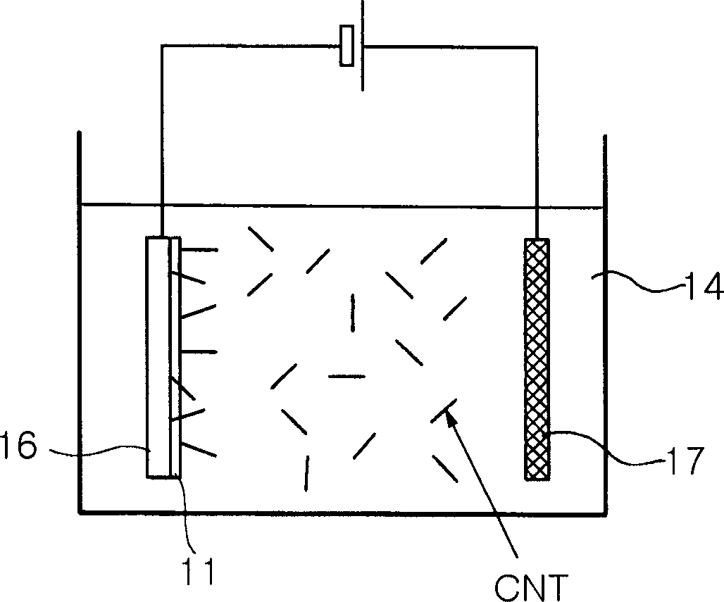
[0037] In this example, in order to achieve uniform dispersion of carbon nanotubes, the carbon nanotube mixture ...


PUM

PropertyMeasurementUnit
lengthaaaaaaaaaa
thicknessaaaaaaaaaa
thicknessaaaaaaaaaa

Abstract

The present invention provides a process for fabricating a field emitter electrode, comprising dispersing carbon nanotubes and a conductive polymer in DI (deionized) water to prepare a carbon nanotube mixture having a viscosity of 50 to 100 cps; applying the carbon nanotube mixture to a substrate; and heat treating the carbon nanotube mixture to form a conductive polymer layer including carbon nanotubes.

Description

[0001] related application [0002] This application claims priority from Korean Application No. 2004-73560 filed on September 14, 2004, the entire disclosure of which is incorporated herein by reference. technical field [0003] The present invention relates to a method for manufacturing a field emission electrode, and more particularly to a novel method for manufacturing a field emission electrode, wherein the disadvantage of low bonding strength of carbon nanotubes exhibited in conventional electrophoresis methods is improved , and the method is simplified. Background technique [0004] In general, a field emission device is a light source based on electron emission in a vacuum, and refers to a light emitting element, based on the principle that electrons emitted from particles are accelerated by a strong electric field to strike a fluorescent material. Compared with conventional lighting sources such as incandescent light bulbs, the above-mentioned field emission device...

Claims


Application Information

Patent Timeline
Patent Type & Authority Applications(China)
IPC IPC(8): H01J9/02C01B31/00
CPCB82Y10/00H01J9/025B82Y40/00H01J1/304H01J2201/30469
Inventor 康蓥同李宗勉
Owner SAMSUNG ELECTRO MECHANICS CO LTD
Why Eureka
Try Eureka