Double end testing method in power transmission line longitudinal difference protection

A technology of longitudinal differential protection and test method, applied in the electrical field, can solve the problems of cumbersome test operation and seldom used, and achieve the effects of good economy, convenient realization, and huge space for popularization and application.

Inactive Publication Date: 2006-03-29
XUJI GRP +2
View PDF0 Cites 8 Cited by
  • Summary
  • Abstract
  • Description
  • Claims
  • Application Information

AI Technical Summary

Problems solved by technology

Due to the influence of economic and geographical factors, this method is rarely used in the field
A Japanese company's optical fiber differential protection device outputs a phase trigger output terminal and a time trigg...

Method used


Image

  • Double end testing method in power transmission line longitudinal difference protection
  • Double end testing method in power transmission line longitudinal difference protection
  • Double end testing method in power transmission line longitudinal difference protection

Examples


Embodiment Construction

[0019] Below in conjunction with accompanying drawing and the present invention is described in further detail.

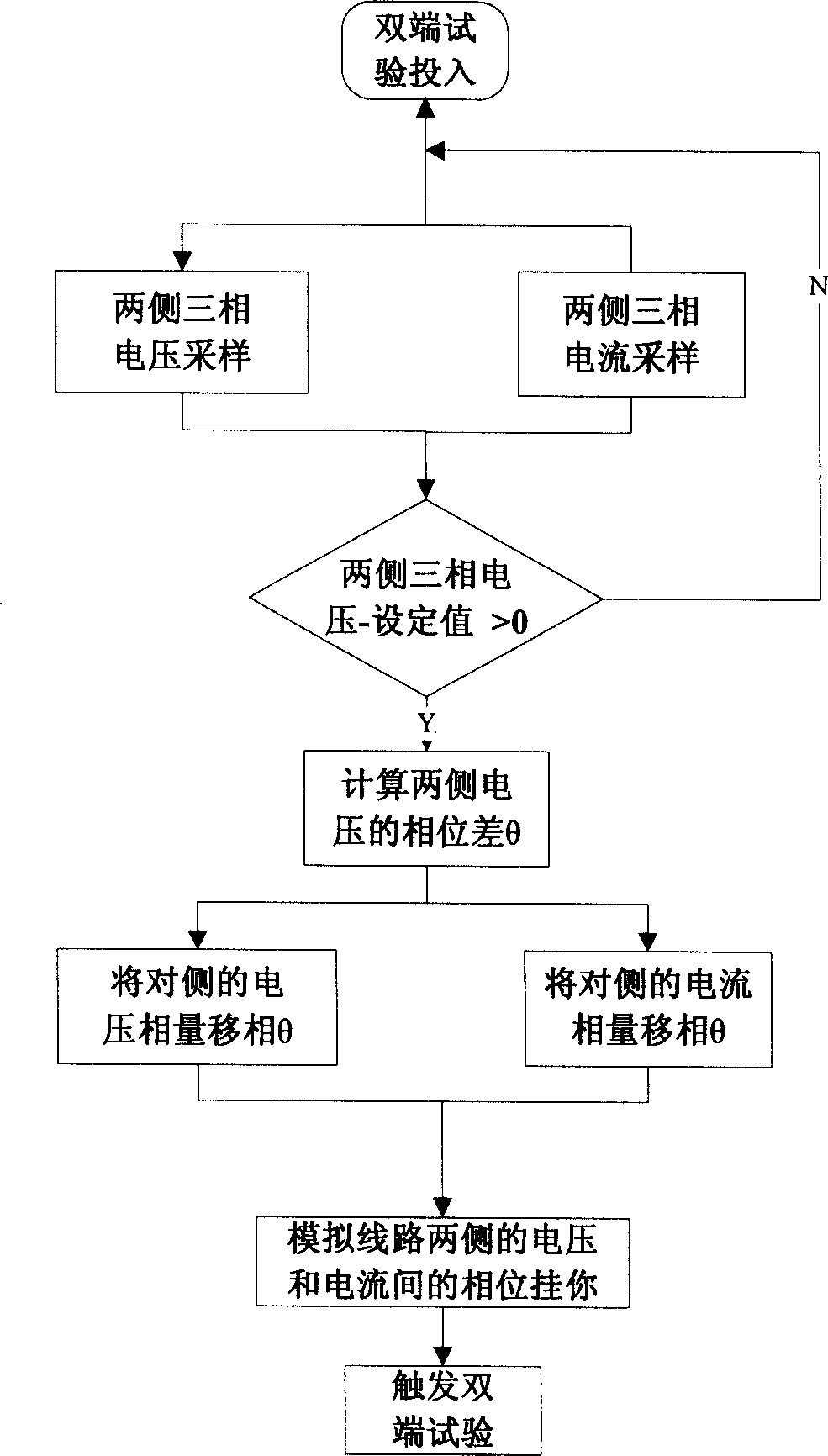
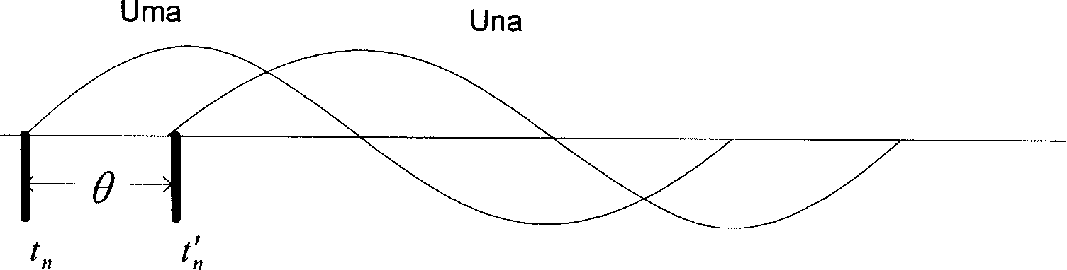
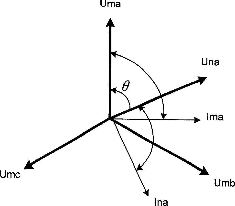
[0020] see figure 1 The flow chart of this double-ended test method first selects the "double-ended test" control item in the protection device to put into the double-ended test function, and then samples the voltage and current on both sides to obtain the following figure 2 The voltage waveform diagram is shown, where Uma is the a-phase voltage on this side, Una is the a-direction voltage on the other side, and θ is the phase difference of the voltage phasors on both sides. Then compare the voltages Uma, Umb, Umc and Una, Unb, Unc on both sides with a specific threshold (set value), and if both are larger than the specific threshold, calculate the phase angle difference θ of the voltage phasors on both sides , otherwise return and continue sampling. After calculating the phase angle difference θ, shift the phase of the voltage phasor on the opposite side to the...


PUM


Abstract

This invention relates to a method for testing double ends in the translay protection of a transmission line including: 1, a protection device transfers the sample values of three-phase current and three-phase voltage, 2, the device computes the theta of the double side voltage based on their sample values when the voltages of both sides are larger than the designed threshold, 3, one side shifts theta of the AC voltage sent by the opposite, then the voltage phases applied by the two-side test instruments are equal, therefore, a unified voltage phase primary standard is set up for the AC output of the instruments, 4, the protection device takes the voltage phasor phase of the two sides as the primary standard of the current phase to adjust the current phase, and a relay protection device can rectify the phase between the voltage and current of its side to carry out the test for protecting both ends, 5, triggering the two-end test.

Description

technical field [0001] The invention relates to a double-terminal test method in the longitudinal differential protection of transmission lines in the electrical field, in particular to a convenient on-site test method provided by adding a double-terminal test function module in the relay protection of a high-voltage power grid, and a built-in double-terminal test method in the protection device The implementation method of the test module. Background technique [0002] The reliability of relay protection devices in high-voltage transmission systems is the guarantee for the safe and stable operation of power systems. Years of on-site operation experience tell us that the reliability of the protection device not only depends on the correctness of the principle and implementation method of the protection device itself, but also depends on the correct wiring of the secondary circuit of the relay protection. Before the relay protection device is put into operation and during th...

Claims


Application Information

Patent Timeline
IPC IPC(8): H02H3/26
Inventor 张克元张项安李瑞生路光辉桑仲庆李峥峰
Owner XUJI GRP
Why Eureka
Try Eureka