Exposure apparatus, exposure method, and method for producing device

An exposure device and component technology, which is applied in semiconductor/solid-state device manufacturing, photolithography exposure device, microlithography exposure equipment, etc., can solve the problems of insufficient formation of liquid immersion area, vibration, liquid splash, etc. Occurrence of exposure blur and environmental changes in which substrates are placed, prevention of environmental changes, and effects of reliable recycling

Inactive Publication Date: 2006-03-29
NIKON CORP
View PDF13 Cites 6 Cited by
  • Summary
  • Abstract
  • Description
  • Claims
  • Application Information

AI Technical Summary

Problems solved by technology

However, it is clearly known that liquid vibration occurs between the projection optical system and the substrate (the so-called water hammer phenomenon), or vibration occurs between the liquid supply device itself (supply pipe and supply nozzle, etc.), causing the problem of deterioration of the pattern image. In addition, because the structure is such that the liquid flows from a single direction relative to the projected area, it is also There is a problem that the liquid immersion area cannot be sufficiently formed between the projection optical system and the substrate
[0008] In addition, in the above-mentioned prior art, since the recovery unit for recovering the liquid recovers the liquid only on the downstream side of the flowing liquid in the moving direction of the above-mentioned substrate, there is also a problem that the liquid cannot be recovered sufficiently.
If the liquid cannot be recovered sufficiently, the liquid will remain on the substrate, and exposure blur may occur due to the remaining liquid.
In addition, if the liquid cannot be completely recovered, the remaining liquid will splash on the surrounding mechanical parts, causing abnormalities such as rusting.
Furthermore, if the liquid remains or splashes, the change in the environment (humidity, etc.) where the substrate is placed will cause changes in the refractive index on the optical path of the detection light of the optical interferometer used in stage position measurement, etc. There is a danger that the desired pattern transfer accuracy cannot be obtained
[0009] In addition, when the liquid on the substrate is recovered with the liquid recovery nozzle, vibration may occur between the liquid recovery device itself (recovery pipe, recovery nozzle, etc.)
If this vibration is transmitted to the projection optical system, the substrate stage, or the optical components of the interferometer used to measure the position of the substrate stage, it may not be possible to form a circuit pattern on the substrate with high precision.

Method used


Image

  • Exposure apparatus, exposure method, and method for producing device
  • Exposure apparatus, exposure method, and method for producing device
  • Exposure apparatus, exposure method, and method for producing device

Examples


Embodiment Construction

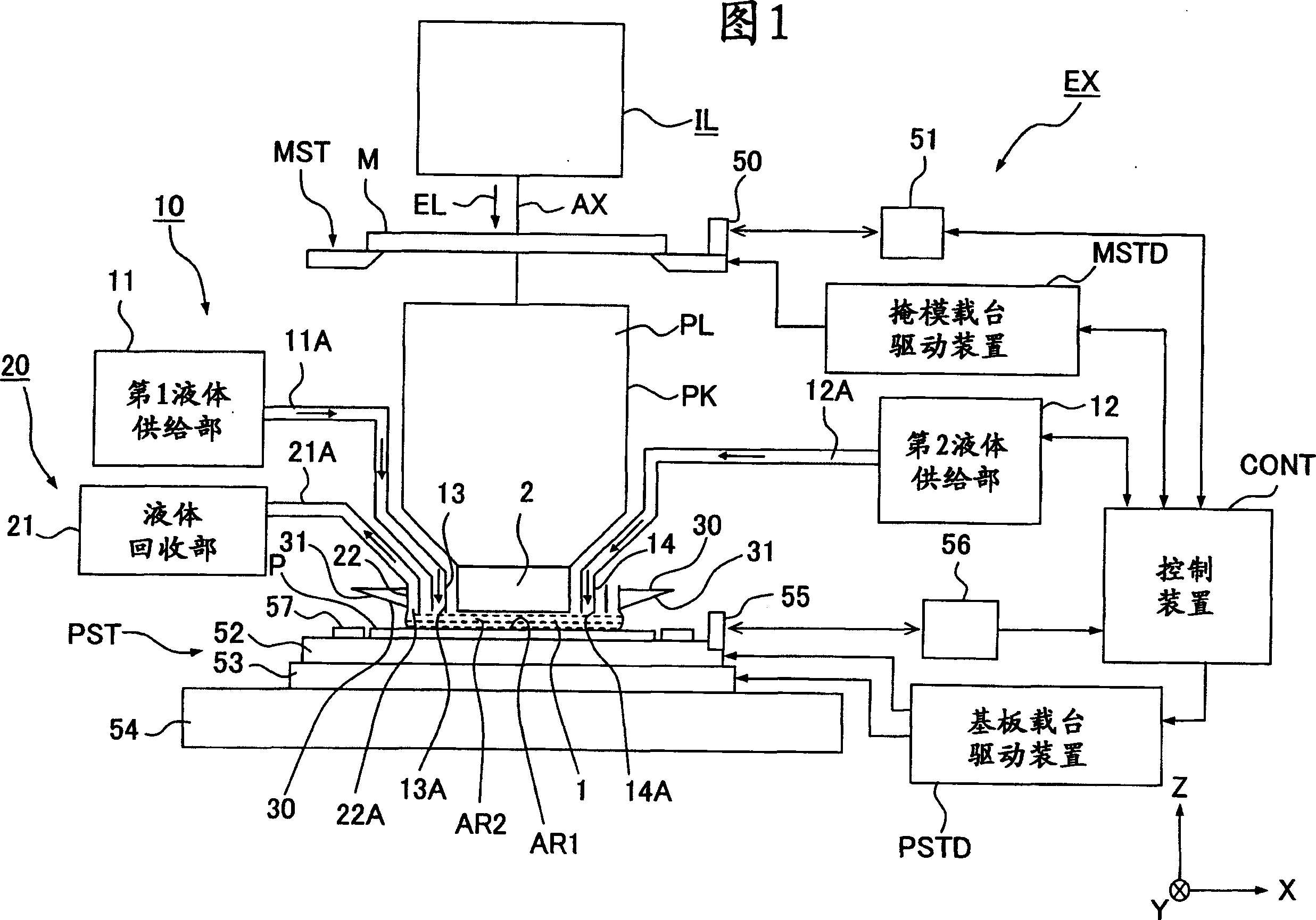
[0096] Hereinafter, the exposure apparatus of this invention is demonstrated with reference to drawings. FIG. 1 is a schematic configuration diagram showing an embodiment of an exposure apparatus of the present invention. In FIG. 1, the exposure apparatus EX includes: a mask stage MST supporting a mask M; a substrate stage PST supporting a substrate P; and an illumination optical system for illuminating the mask M supported by the mask stage MST with an exposure light beam EL. IL; the projection optical system PL for projecting and exposing the pattern image of the mask M illuminated by the exposure light beam EL onto the substrate P supported by the substrate stage PST; and the control device CONT for overall controlling the overall operation of the exposure device EX.

[0097] In addition, the exposure apparatus EX of this embodiment is a liquid immersion exposure apparatus to which a liquid immersion method is applied in order to substantially increase the depth of focus wh...


PUM

PropertyMeasurementUnit
refractive indexaaaaaaaaaa

Abstract

An exposure apparatus exposes a substrate by projecting an image of a predetermined pattern through a liquid onto the substrate. The exposure apparatus includes a projection optical system which performs the projection, and a liquid supply mechanism which supplies the liquid onto the substrate to form a liquid immersion area on a part of the substrate. The liquid supply mechanism supplies the liquid onto the substrate simultaneously from a plurality of positions which are apart, in a plurality of different directions, from the projection area. The exposure apparatus is capable of forming the liquid immersion area stably and recovering the liquid satisfactorily. It is possible to perform the exposure process accurately while avoiding the outflow of the liquid to the surroundings.

Description

technical field [0001] The present invention relates to an exposure device, an exposure method, and a device manufacturing method for exposing a pattern on a substrate in a state where a liquid immersion region is formed between a projection optical system and the substrate. Background technique [0002] Semiconductor devices and liquid crystal display devices are manufactured by a method called photolithography in which a pattern formed on a mask is transferred to a photosensitive substrate. The exposure apparatus used in this photolithography process has a mask stage that supports the mask and a substrate stage that supports the substrate, and moves the mask stage and the substrate stage sequentially while projecting the pattern of the mask through the projection optical system. Devices transferred onto substrates. In recent years, in order to cope with the further high integration of device patterns, further high resolution of the projection optical system is desired. T...

Claims


Application Information

Patent Timeline
Patent Type & Authority Applications(China)
IPC IPC(8): H01L21/027G03F7/20
CPCG03F7/70341G03F7/7095
Inventor 长坂博之大和壮一西井康文
Owner NIKON CORP
Why Eureka
Try Eureka