Air conditioner
A technology of air conditioner and pressure reducer, which is applied in the direction of high-efficiency regulation technology, compression machine with reversible cycle, damage protection, etc. It can solve the problems of increased pressure loss, enlarged heater structure, and increased refrigerant circulation volume, etc. Achieve the effects of small pressure fluctuations, reduced volume, and improved operational reliability
- Summary
- Abstract
- Description
- Claims
- Application Information
AI Technical Summary
Problems solved by technology
Method used
Image

Examples
Embodiment 1
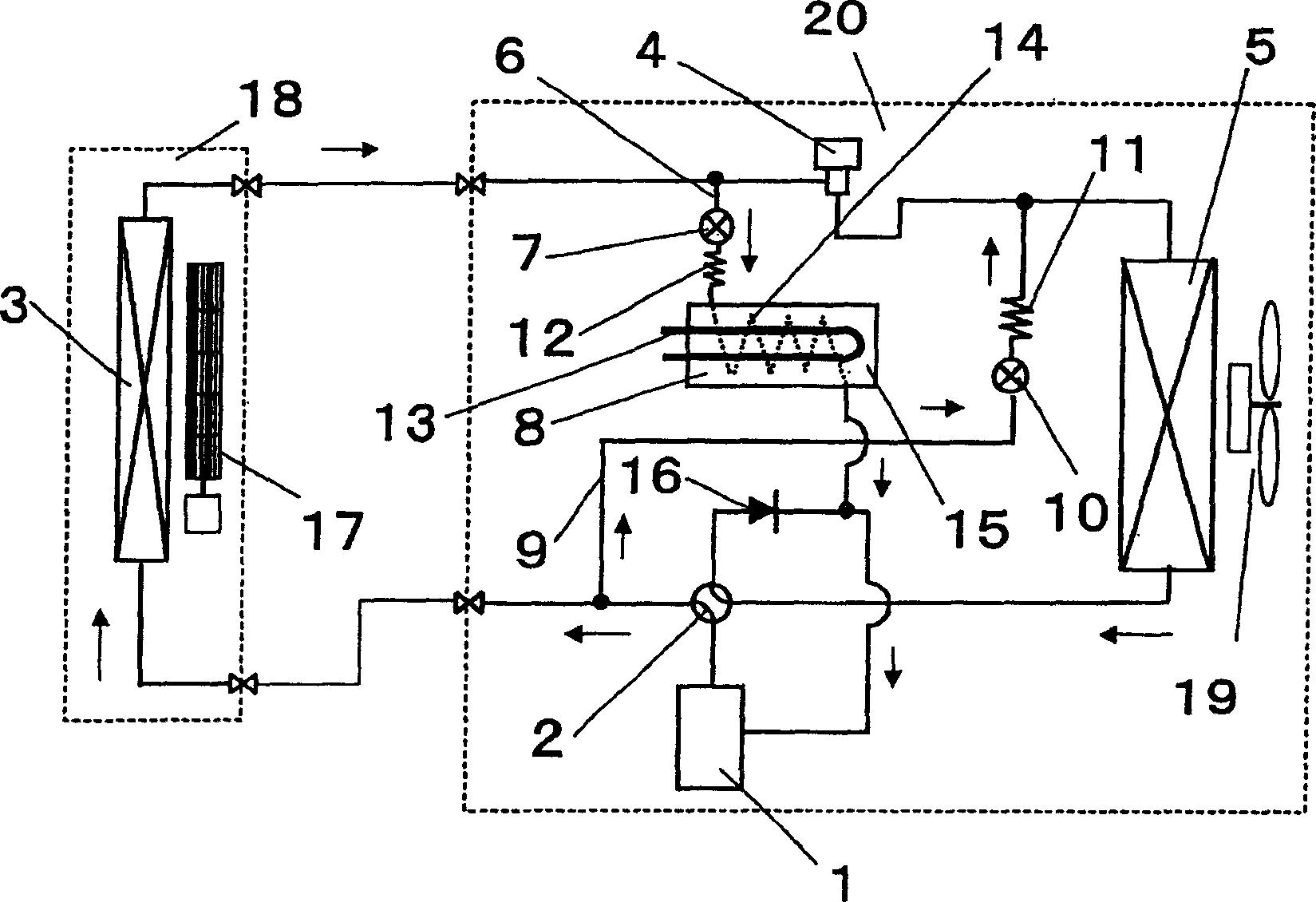
[0041] figure 1 It is a structural diagram of the air conditioner in the present invention. exist figure 1 Among them, the outdoor unit 20 is equipped with: a compressor 1, a four-way valve 2, a pressure reducer 4, an outdoor heat exchanger 5, a first bypass circuit 6, a two-way valve for refrigerant heating 7, and a refrigerant heater 8. The second bypass circuit 9, the two-way valve 10 for defrosting, the two-way valve 11 of the second bypass circuit, the two-way valve 12 of the first bypass circuit, the refrigerant heating device 13, and the refrigerant passing pipe 14 , heat storage unit 15, check valve 16 and outdoor fan 19. The indoor unit 18 is provided with an indoor heat exchanger 3 and an indoor fan 17 . The pressure reducer 4 here may be an electromagnetic expansion valve.
[0042] Figure 4 Shown in the control system block diagram of embodiment 1 of the present invention, Figure 5 The working sequence diagram for the operation of the control system. Fig...
Embodiment 2
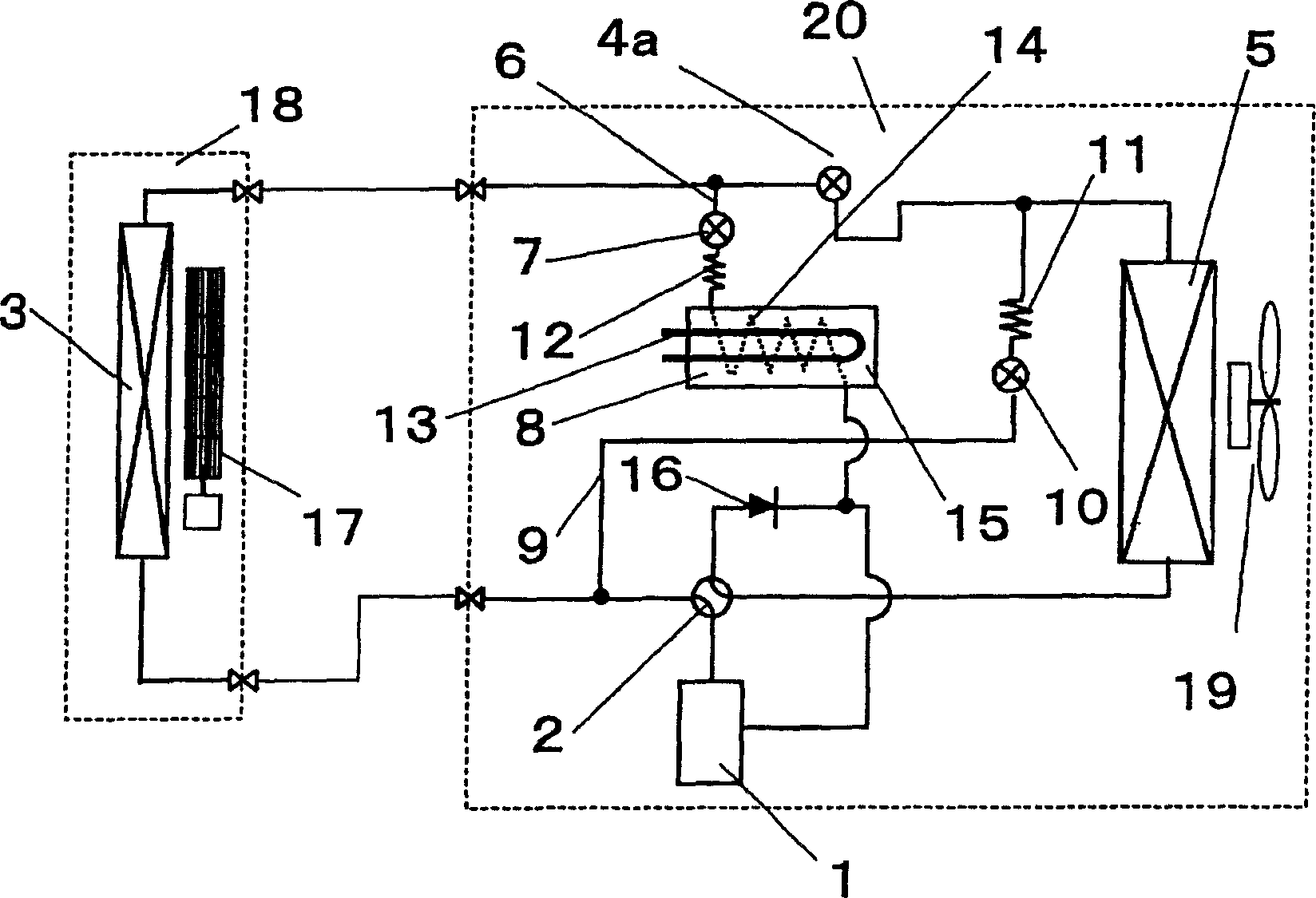
[0053] Next, pass figure 2 Embodiment 2 of the present invention will be described.
[0054] The difference between the present embodiment and the first embodiment is that the decompressor 4 is constituted by using a two-way valve 4 a that does not have a depressurization function but only performs opening and closing operations of the refrigerant. In such a case, defrosting may be performed while continuing heating.
[0055] The operation of the two-way valve 4a is as follows. At the same time as the two-way valve 7 for refrigerant heating is controlled to be opened or a little later, the two-way valve 4a is controlled to be closed.
Embodiment 3
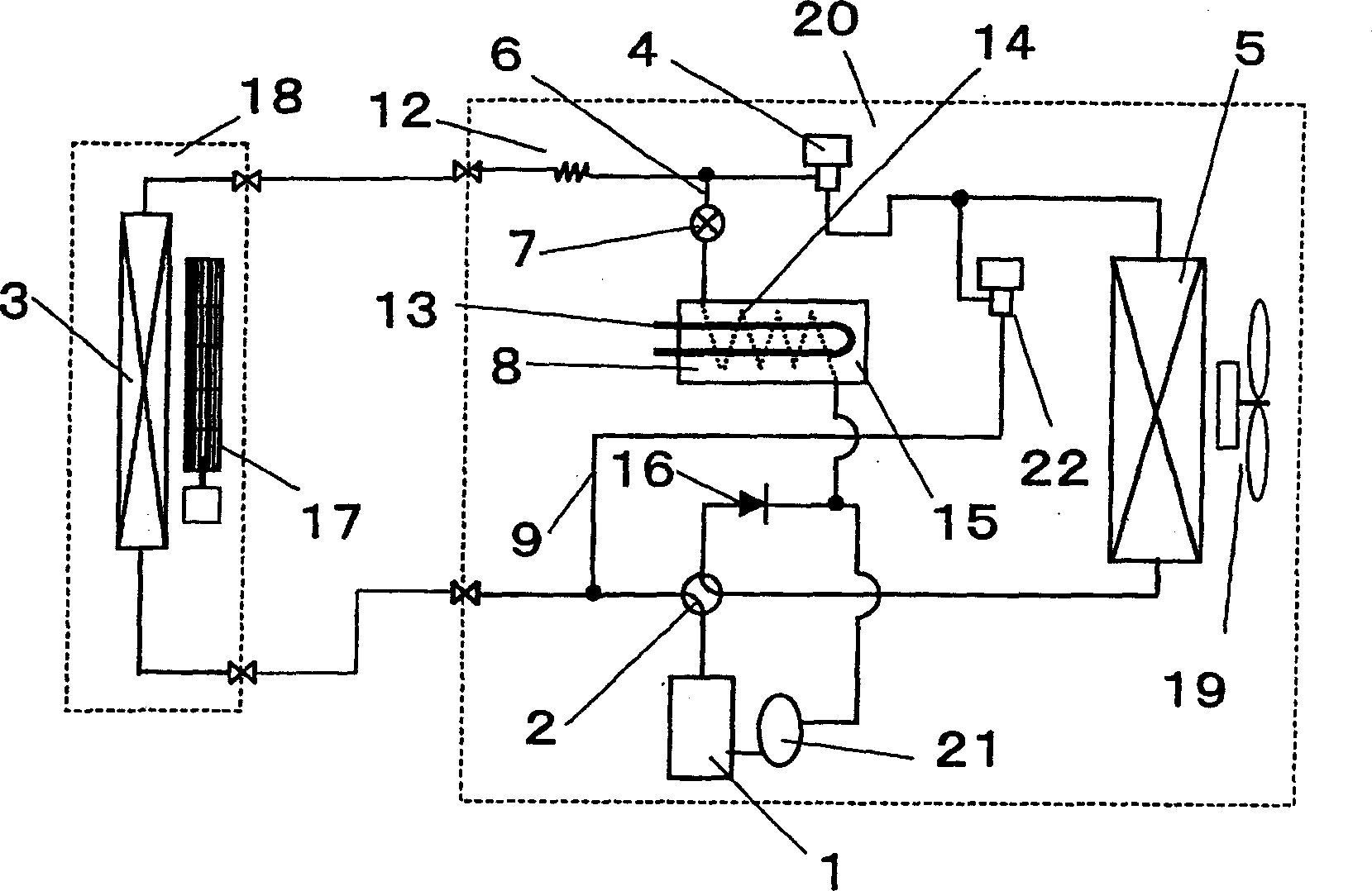
[0057] pass below image 3 Embodiment 3 will be described.
[0058] The difference between this embodiment and Embodiment 1 is that there is no pressure reducer between the two-way valve 7 for heating the refrigerant and the heater 8, but a pressure reducer between the indoor heat exchanger 3 and the pressure reducer 4 Reducer 12.
[0059] With such an arrangement, the first bypass circuit 6 can be simplified, thereby reducing the volume of the body and reducing the manufacturing cost.
[0060] In addition, a gas-liquid separator 21 is provided on the suction side of the compressor 1 .
[0061] Due to the different specifications of the compressors 1 , some compressors 1 have a weaker tolerance to liquid return. In such a case, it is necessary to provide such a gas-liquid separator 21 .
[0062] In particular, liquid return is more during defrosting operation, so the impact of liquid return on compressor reliability needs to be considered.
[0063] In addition, by constit...
PUM
 Abstract
Description
Claims
Application Information
 - Generate Ideas
- Intellectual Property
- Life Sciences
- Materials
- Tech Scout
- Unparalleled Data Quality
- Higher Quality Content
- 60% Fewer Hallucinations
Browse by: Latest US Patents, China's latest patents, Technical Efficacy Thesaurus, Application Domain, Technology Topic, Popular Technical Reports.
© 2025 PatSnap. All rights reserved.Legal|Privacy policy|Modern Slavery Act Transparency Statement|Sitemap|About US| Contact US: help@patsnap.com