

Chain guide
A technology of guides and chains, which is applied to belts/chains/gears, transmissions, mechanical equipment, etc., can solve the problems of chain guide model changes and increase manufacturing costs, and achieve the effect of simplifying changes and increasing bending stiffness
- Summary
- Abstract
- Description
- Claims
- Application Information
AI Technical Summary
Problems solved by technology
Method used
Image

Examples
no. 1 Embodiment
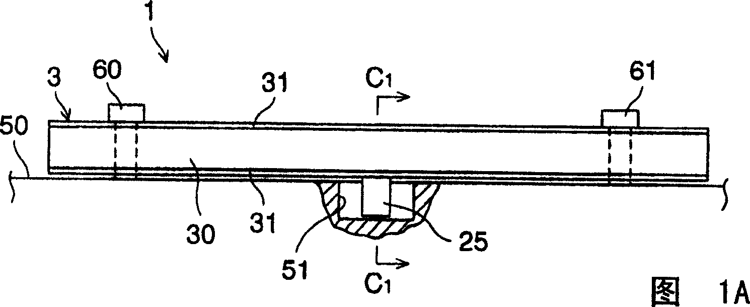
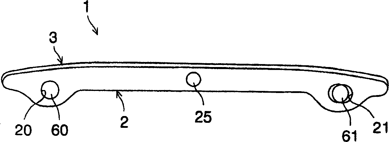
[0029] As shown in FIGS. 1A to 1C , the chain guide 1 includes a guide body 2 . The guide body is preferably made of synthetic resin, aluminum die casting, or the like. The chain guide 1 also comprises a guide plate 3, preferably made of synthetic resin or similar material, fixedly connected to the guide body 2 or integral with the guide body.
[0030] A pair of bolt holes 20, 21 are formed at opposite ends of the guide body 2 for receiving mounting bolts 60, 61 to mount the chain guide 1 on an engine part, such as an engine block (or engine front cover) 50. The bolt hole 21 is preferably an elongated hole extending along the length of the guide body 2, i.e. at Figure 1B Stretched in the left and right directions, in order to absorb the thermal expansion of the guide body 2 caused by the temperature rise of the engine during operation.
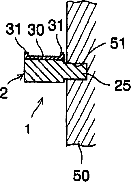
[0031] An engaging protrusion 25 protruding from the side of the guide body 2 is provided at a central position in the elongate direction o...
no. 2 Embodiment
[0037] Figures 2A to 2C Shows the second embodiment of the present invention. In the figures, the same reference numerals denote identical or functionally identical elements.
[0038] In the second embodiment, contrary to the first embodiment, the engaging protrusion 52 is preferably installed on the engine block 50 side, and the engaging hole 22 engageable with the engaging protrusion 52 is preferably formed at the center of the guide body 2 in the elongated direction. Location. The engagement protrusion 52 is preferably a solid cylindrical protrusion or a prismatic protrusion. In operation, when the chain transmits pressure, the guide body 2 is supported by the engaging protrusion 52 of the engine block 50, so that the bending rigidity of the entire chain guide is increased as in the first embodiment of the present invention. Also, since the engaging protrusion 52 of the motor block 50 is only inserted into the engaging hole 22 of the guide body 2, cost increase is limit...
no. 3 Embodiment
[0041] Figures 3A to 3C A third embodiment of the present invention is shown. In the figures, the same reference numerals denote identical or functionally identical elements.
[0042] In the third embodiment, contrary to the first and second embodiments, a flat-shaped protrusion 53 is formed on the engine block 50 side, and the lower surface of the guide body 2 is supported from below by the flat-shaped protrusion 53 .
[0043]In operation, when the chain transmits pressure, the guide body 2 is supported by the plate-shaped protrusion 53 of the engine block 50, so the bending rigidity of the entire chain guide is increased as in the first and second embodiments of the present invention. Also, since the flat-shaped protrusion 53 is mounted only on the engine block 50, increase in cost is limited without significantly increasing the size and vertical of the entire chain guide and without changing the model of the chain guide. Also, since the flat plate-shaped protrusion 53 of...
PUM
 Abstract
Description
Claims
Application Information