Robot overcurrent prevention system

An overcurrent and robot technology, applied in the field of robots, can solve the problems of robots stopping work and unstable posture, and achieve the effects of protecting the electrical system, eliminating noise, and reliably detecting overcurrent.

Inactive Publication Date: 2006-04-26
HONDA MOTOR CO LTD
View PDF1 Cites 9 Cited by
  • Summary
  • Abstract
  • Description
  • Claims
  • Application Information

AI Technical Summary

Problems solved by technology

[0004] In this structure, when an overcurrent is detected, the electrical system can be protected by suppressing energization, but depending on the situation, the robot may stop working or its posture may become unstable.

Method used


Image

  • Robot overcurrent prevention system
  • Robot overcurrent prevention system
  • Robot overcurrent prevention system

Examples


Embodiment 1

[0037] Next, an overcurrent prevention device for a robot according to a first embodiment of the present invention will be described with reference to the drawings.

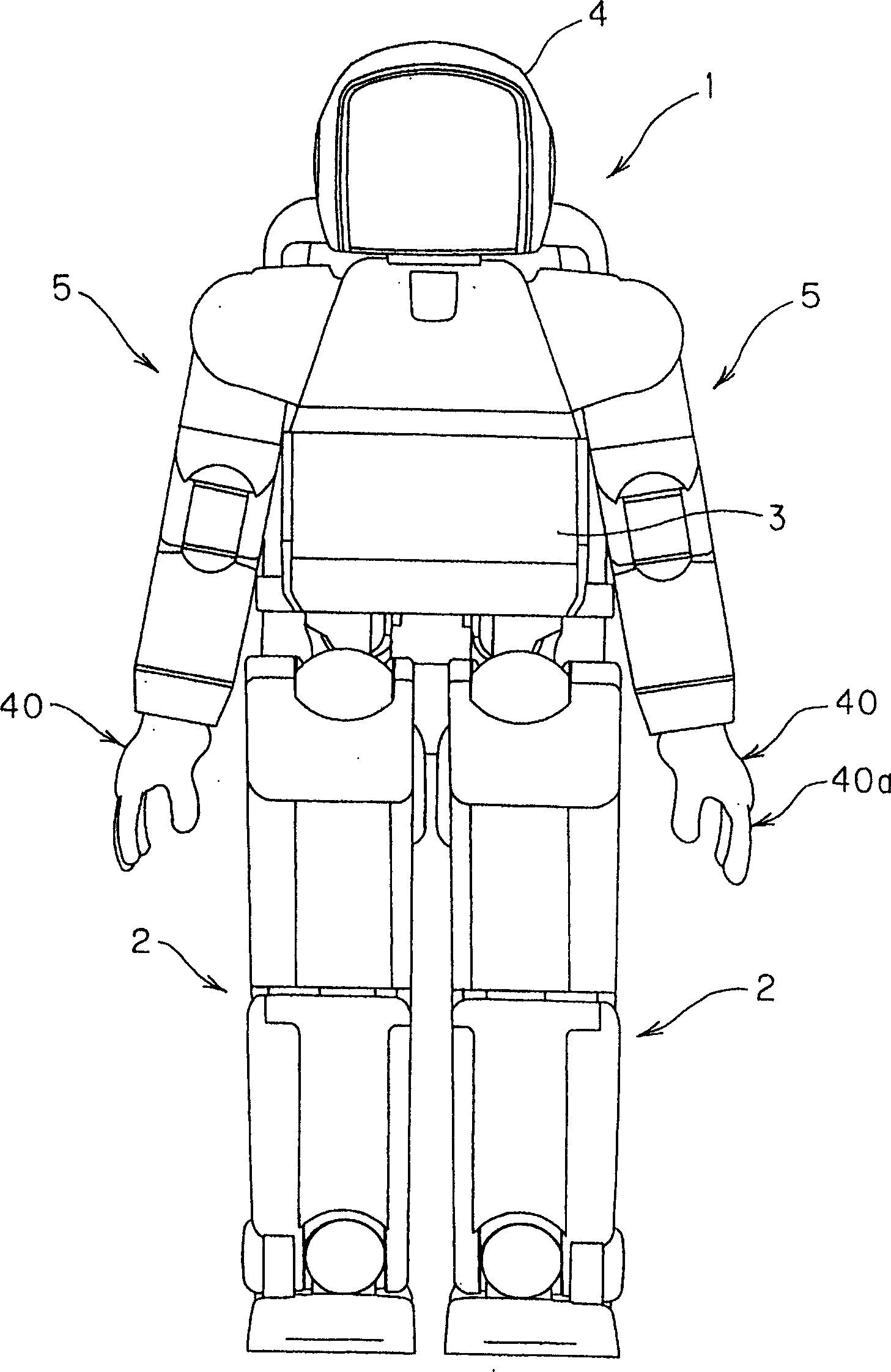
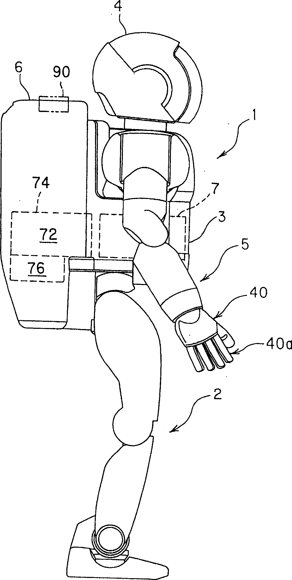
[0038] figure 1 It is a front view showing a robot as an object of the overcurrent prevention device of the first embodiment, figure 2is a side view of the robot. In addition, the robot is a legged mobile robot, and more specifically, there is, for example, a human-shaped legged mobile robot having two legs and two arms.

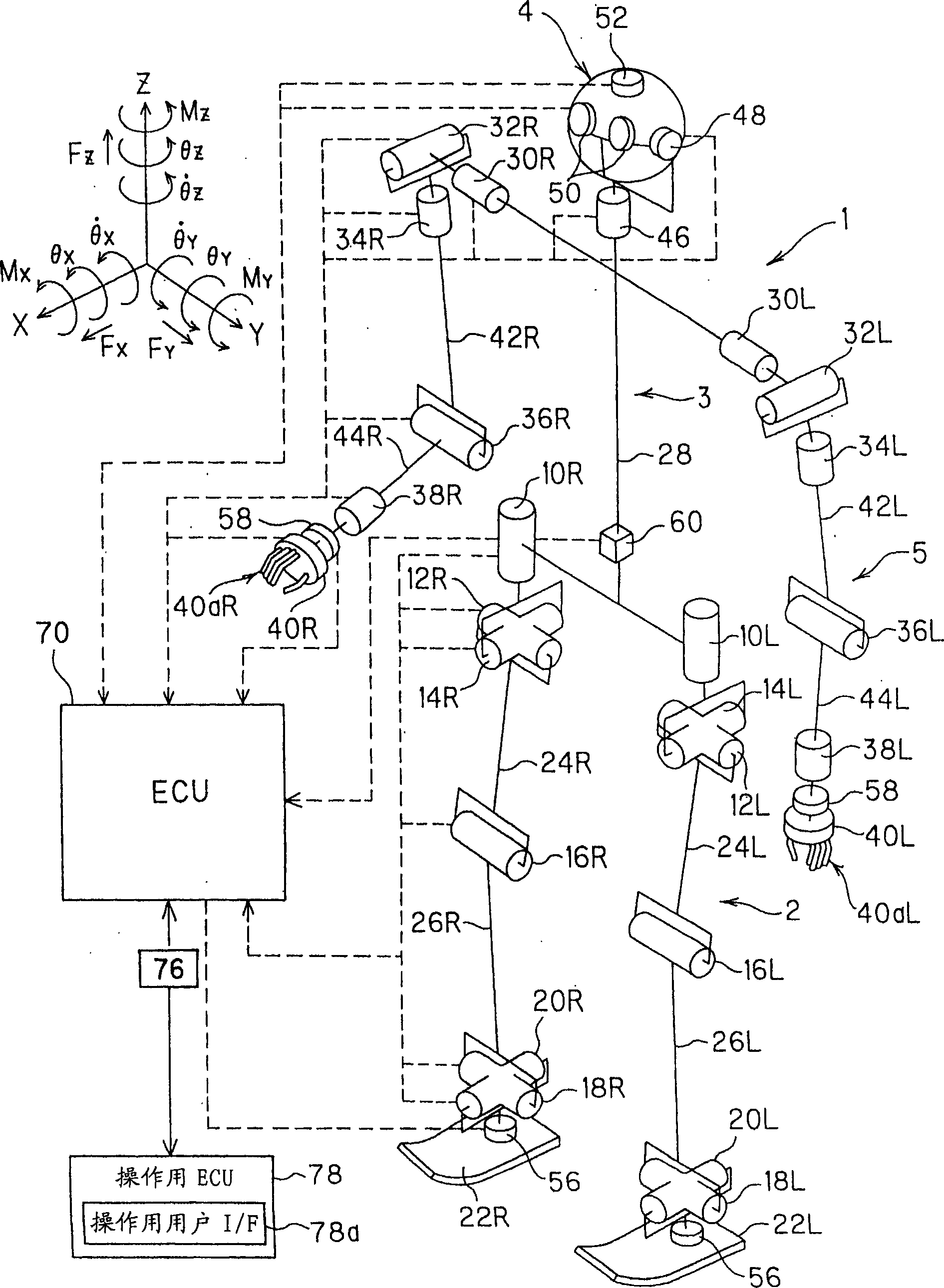
[0039] Such as figure 1 As shown, a robot (more specifically a legged mobile robot) 1 has multiple, more specifically two (bar) legs 2, and a base (upper body) 3 is provided above the legs 2. A head portion 4 is formed above the base body 3 , and two (bar) arm portions 5 are connected to both sides of the base body 3 . Additionally, if figure 2 As shown, a receiving portion 6 is provided on the back of the base body 3 . A battery (voltage source) 7 is housed inside the base body 3 , and...

Embodiment 2

[0088] Figure 11 represent the overcurrent prevention device of the second embodiment of the present invention and Figure 5 Same block diagram.

[0089] The description will focus on the difference from the first embodiment. In the second embodiment, a temperature sensor 90 is provided to detect the outside air temperature TA, the threshold value Va and the predetermined time T2 (first predetermined time) are changed according to the detected value, and the ECU 70 (more precisely, the CPU 70a) has an overcurrent prevention unit 70a4 that performs an overcurrent prevention operation using software technology.

[0090] Such as figure 2 As shown by the dotted line, in the second embodiment, the temperature sensor 90 is specifically arranged at an appropriate position facing the outside of the housing portion 6 to output a signal representing the external air temperature TA around the robot 1 . In addition, the same code|symbol is attached|subjected to the same member as 1st...

Embodiment 3

[0104] Figure 14 represent the overcurrent prevention device of the third embodiment of the present invention and Figure 6 Same block diagram.

[0105] The description will focus on the differences from the first and second embodiments. In the third embodiment, the structure of the first embodiment is used to realize a structure similar to that of the second embodiment. That is, separate from the ECU 70, the second ECU (ECU 2) 92 constituted by a single-chip microcomputer is installed near the temperature sensor 90 and connected by an appropriate cable (not shown), and the output TA of the temperature sensor 90 is input to the temperature sensor 90. To the 2nd ECU 92, the 2nd ECU 92 changes the value equivalent to the threshold value Va to be input to the one input terminal of the comparator 80c according to this input value.

[0106] More specifically, the output TA of the temperature sensor 90 is A / D converted and input to the second ECU 92, and the second ECU 92 follows...


PUM


Abstract

The present invention provides an overcurrent prevention device for a robot, which protects an electrical system when an overcurrent is detected, and prevents a robot from being disabled or unstable in its posture regardless of the situation. It includes: FET (80a), which is inserted in the power supply circuit (7a), and when it is turned off, cuts off the power supply circuit (7a) to stop the power supply to the drive circuit (72); a current sensor (80b), which generates The output corresponding to the current of the motor energization; and the overcurrent suppression unit (comparator (80c), the first and second delay circuits (80d, 80e), EX-OR circuit (80f), AND circuit (80g), oscillator ( 80h), buffer (80i), AND circuit (80j), insulated gate driver (80k), latch circuit (801), ECU (70)), which compares the output V1 of the current sensor with the threshold Va, when the current When the output of the sensor exceeds the threshold value, the switching operation of turning on/off the switching element is performed within a first predetermined time (T2) to intermittently shut off the power supply circuit.

Description

technical field [0001] The present invention relates to robots, and more particularly to an overcurrent preventing device for a legged mobile robot. Background technique [0002] In robots, in general, the current flowing in the motor that drives the joint is detected, and an overcurrent is detected by comparing with a threshold value, and when an overcurrent flows, the electrical system such as the motor is protected by suppressing the current. As prior art, a device disclosed in Patent Document 1 below is known. In the technology of Patent Document 1, in the device for driving and controlling the servo motor according to the supplied servo command, the threshold value can be changed according to the servo command to improve the servo performance at high speed and reduce the current abnormality at low speed Detection accuracy. [0003] Patent Document 1: Japanese Patent Laid-Open No. 2001-022446 [0004] In this configuration, when an overcurrent is detected, the electri...

Claims


Application Information

Patent Timeline
Patent Type & Authority Applications(China)
IPC IPC(8): B25J19/06B25J5/00
Inventor 小柳拓郎岛田贵通
Owner HONDA MOTOR CO LTD
Why Eureka
Try Eureka