Electricity driven traveling wave thermoacoustic refrigerator system

A technology of thermoacoustic refrigerator and electric drive, which is applied in the direction of refrigerator, gas cycle refrigerator, refrigeration and liquefaction, etc. It can solve the problems of large pressure wave generator, difficult manufacturing, difficult to adjust the phase of pressure wave and velocity wave, etc. Achieve the effect of reducing heat loss, improving performance and suppressing circulation

Inactive Publication Date: 2006-05-03
TECHNICAL INST OF PHYSICS & CHEMISTRY - CHINESE ACAD OF SCI
View PDF0 Cites 10 Cited by
  • Summary
  • Abstract
  • Description
  • Claims
  • Application Information

AI Technical Summary

Problems solved by technology

[0006] The purpose of the present invention is to solve the problem in the prior art that it is difficult to adjust the phase of the pressure wave and the velocity wave in the compression chamber by using the inertial tube and the sound volume of the traveling wave refrigerat

Method used


Image

  • Electricity driven traveling wave thermoacoustic refrigerator system
  • Electricity driven traveling wave thermoacoustic refrigerator system
  • Electricity driven traveling wave thermoacoustic refrigerator system

Examples


Embodiment 1

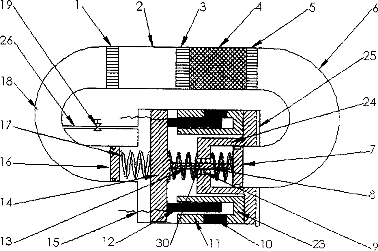
[0041] The structure of embodiment 1 is as figure 1 As shown, it includes a room temperature heat exchanger 1, a thermal buffer pipe 2, a cold end heat exchanger 3, a regenerator 4 filled with wire mesh made of stainless steel or brass, a hot end heat exchanger 5, and an annular connecting pipe connected in sequence. , which also includes a pressure wave generator installed in the annular duct. In this embodiment, one end of the pressure wave generator is connected to the "U"-shaped connecting pipe 6 derived from the hot-end heat exchanger 5, and this connecting pipe is called the hot-end pipe 6; the other end is connected to the auxiliary room temperature heat exchanger 1. The "U"-shaped connecting pipe 18 is called the room temperature pipe 18. The role of the auxiliary room temperature heat exchanger 1 and the thermal buffer pipe 2 is to prevent the gas oscillating back and forth from bringing heat to the cold end heat exchanger 3, which increases the loss of cooling capa...

Embodiment 2

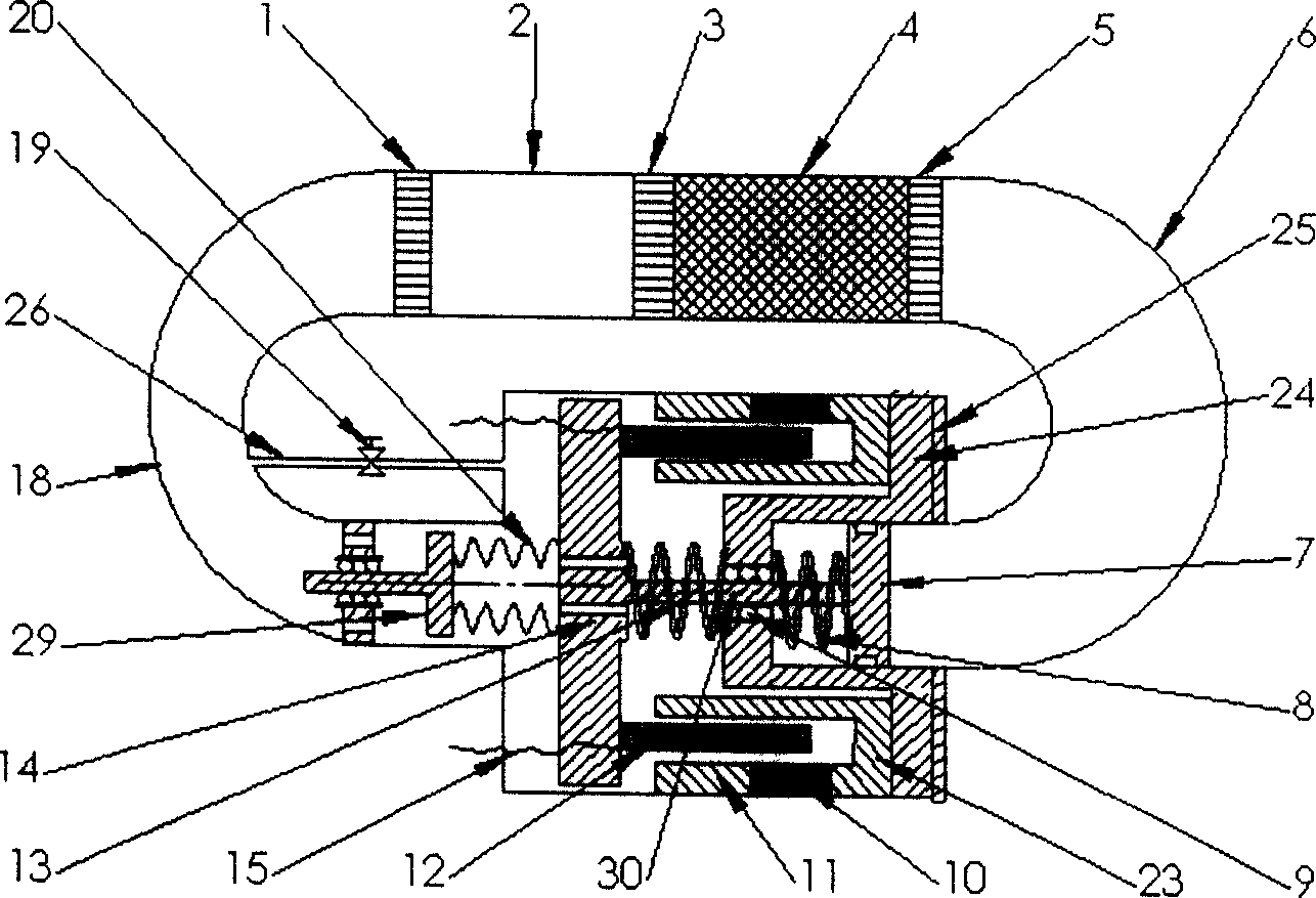
[0044] like figure 2 As shown, in this embodiment, on the basis of embodiment 1, a metal bellows 20 is used to replace the mechanical spring 17 in embodiment 1, and a mass 29 is used to replace the phase-modulating piston 16 in embodiment 1; at the same time, a linear sliding The mass 29 is supported by a bearing or a leaf spring; a gas channel is added on the end face of the coil support 14, so that when the auxiliary bellows vibrates, the internal gas will not generate too much pressure fluctuation and damage the bellows. The metal bellows in this embodiment can be made of ordinary stainless steel 304, beryllium bronze and other materials. The fabrication method is usually hydroforming or welding. Generally, hydroformed bellows are stiffer than welded bellows, so they are more stable.

[0045] When working, the metal bellows 20 plays the role of the mechanical spring 17 in the first embodiment, the mass block 29 plays the role of the phase adjustment piston 16 in the firs...

Embodiment 3

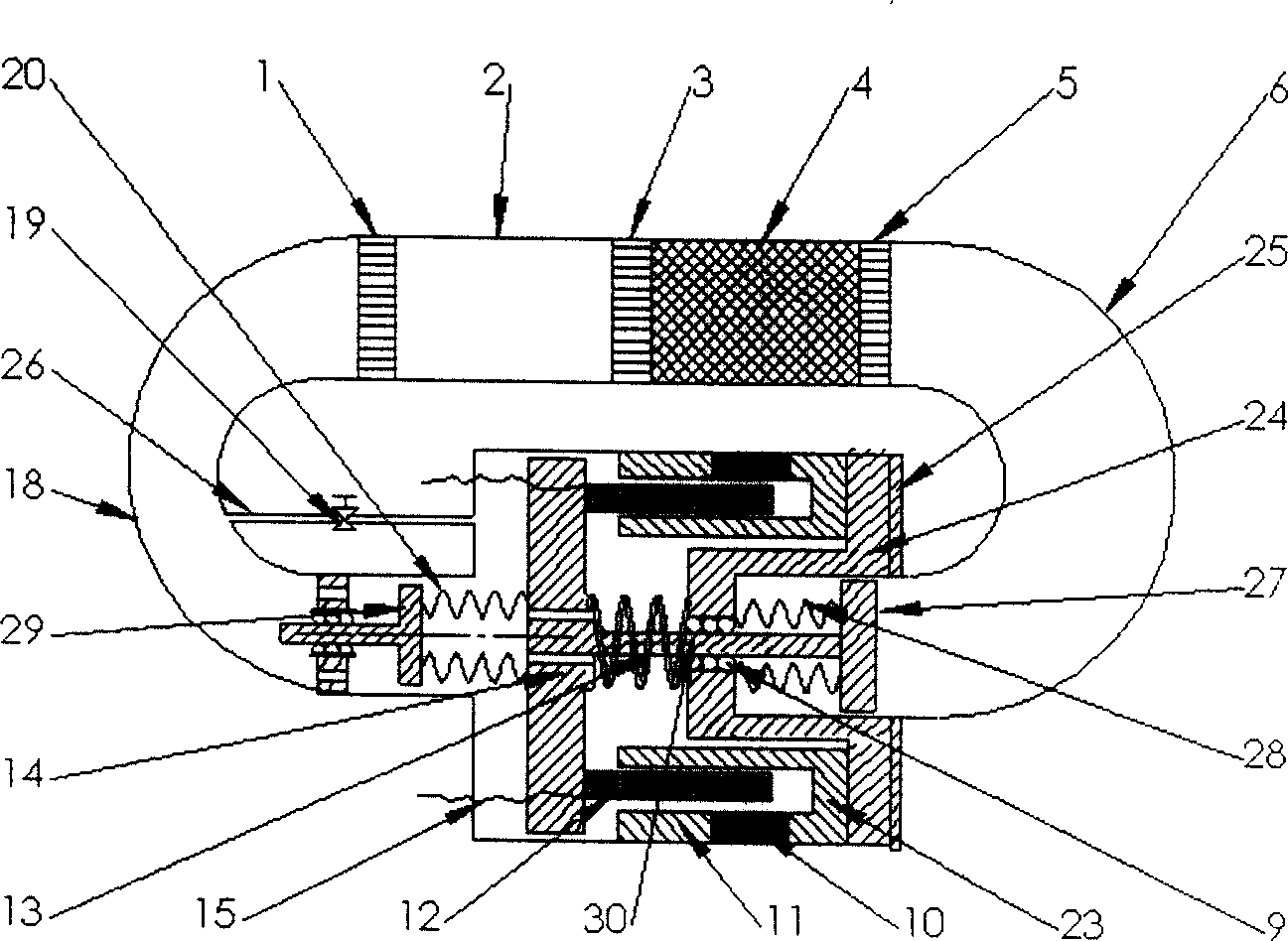
[0047] The structure of this embodiment is as image 3 Shown, it is transformed on the basis of embodiment 2. In this embodiment, the spring-piston assembly in Embodiment 2 is replaced by the bellows-mass assembly as the scavenging elastic-mass assembly, and the materials, manufacturing processes and connection methods of the remaining parts are the same as those in Embodiment 2. The bellows-mass assembly is composed of a metal bellows 28 and a mass 27, and the linear sliding bearing 9 is fixedly connected with the mass 27 to play a supporting role.


PUM


Abstract

The invention discloses a traveling-wave thermoacoustic refrigerating system, which comprises the following loop parts in sequence: cold junction heat exchanger, heat regenerator, heater, heat buffer pipe, hot junction heat exchanger, ring-shaped connection pipe and pressure-wave generator in the pipe, wherein the generator contains a cylinder with one end of casing on the pipe and the other end within line sliding bearing; a double-loop magnetic-inductive soft iron with ring orifice is set in the cavity between cylinder and casing; the permanent magnet is inserted in the outer ring magnetic wall of soft iron; the coil rack is fixed on cylinder inner wall with part of coil in the ring orifice; the elastic or quality component is set in the hot junction pipe; the quality component does shift sliding along the elastic element; the elastic or quality phase modulation component is set in the greenhouse pipe; the quality component does shift sliding along the elastic phase modulation element in the pipe periodically. The invention can adjust the phase difference of pressure fluctuation and bulk flow fluctuation, which feedbacks the acoustic power to accomplish high effective Stirling cycle as well as inhibits the loop ring current to improve property of entire machine.

Description

technical field [0001] The invention relates to the technical field of refrigeration and low temperature, in particular to an electrically driven traveling wave thermoacoustic refrigeration system. Background technique [0002] For a conventional traveling-wave thermoacoustic refrigerator, the sound work input into the system from the pressure wave generator is expressed by the following equation: [0003] W = 1 2 Re [ p ~ U * ~ ] = 1 2 | p ~ U ~ | cos Φ pu = VΩ 4 | p ~ | · cos Φ ...

Claims


Application Information

Patent Timeline
IPC IPC(8): F25B23/00
CPCF25B9/145F25B2309/1403F25B2309/1405
Inventor 罗二仓吴张华戴巍
Owner TECHNICAL INST OF PHYSICS & CHEMISTRY - CHINESE ACAD OF SCI
Why Eureka
Try Eureka