

Electricity generating system driven by traveling wave thermoacoustic engine
A power generation system, thermoacoustic technology, applied in the direction of mechanical power generation mechanisms, machines/engines, lighting and heating equipment, etc., can solve the problem of the non-adjustability of the ejector and the compression piston, the increase of the volume and weight of the acoustic-electric conversion, and the aggravation Compression piston wear and other problems, to achieve the effect of miniaturization, improve reliability, and suppress circulation
- Summary
- Abstract
- Description
- Claims
- Application Information
AI Technical Summary
Problems solved by technology
Method used
Image

Examples
Embodiment 1
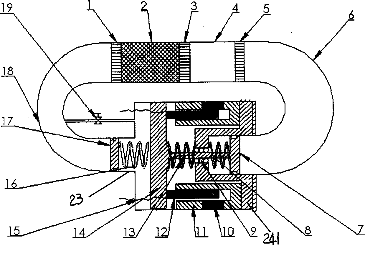
[0054] The structure of embodiment 1 is as figure 1 As shown, it includes a cold-end heat exchanger 1, a heat regenerator 2, a heater 3, a thermal buffer pipe 4, a hot-end heat exchanger 5 and an annular connecting pipe that are connected in sequence and form a loop, and also includes a ring-shaped connecting pipe installed on the in the linear generator. In this embodiment, one end of the linear generator is connected to the "U"-shaped connecting pipe derived from the room temperature heat exchanger 5, and the connecting pipe is called the room temperature pipe 6; The "U"-shaped connecting pipe is called the cold-end pipe 18 . When heat enters the system from the heater 3, a temperature difference appears at both ends of the regenerator 2, and a temperature gradient is established in the axial direction of the regenerator 2. When the temperature gradient is greater than the critical temperature gradient, the traveling-wave thermoacoustic Stirling engine generates self-excit...
Embodiment 2
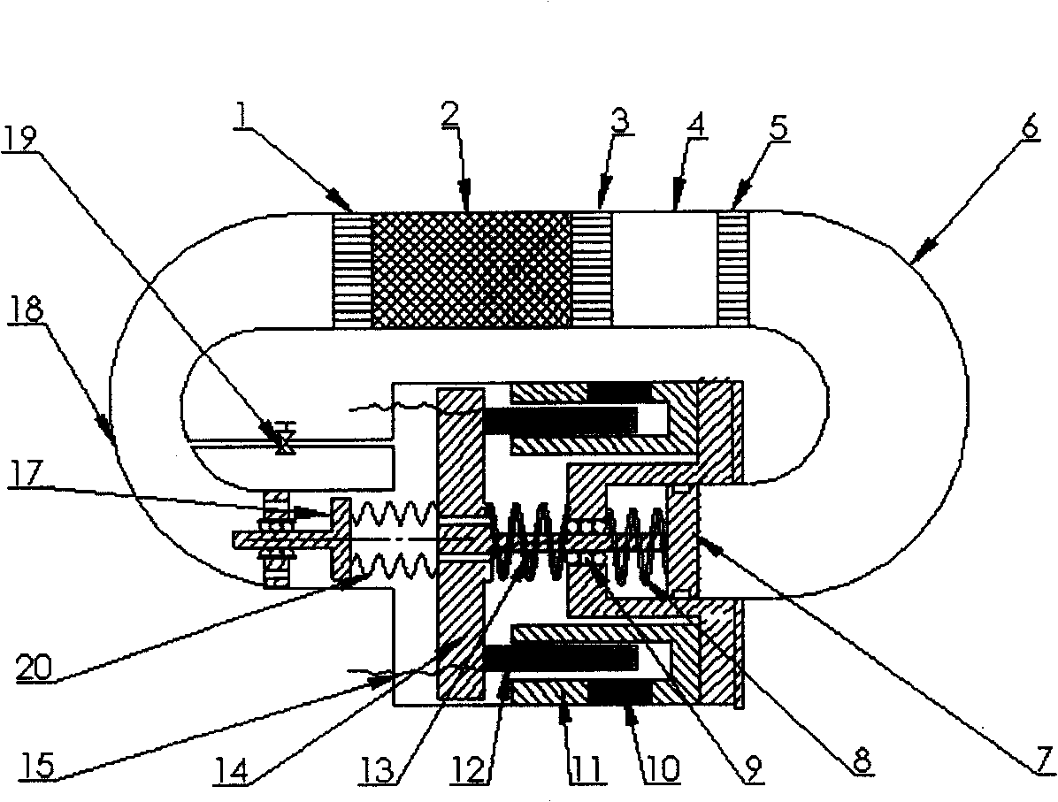
[0062] Such as figure 2 As shown, in this embodiment, on the basis of embodiment 1, a metal bellows 20 is used to replace the phase-modulating elastic element 16 in embodiment 1, and a mass block is used to replace the mass element 17 in embodiment 1; at the same time, a linear sliding Bearings or leaf springs are used to support the mass; gas passages are added on the end face of the coil support 14, so that when the auxiliary bellows vibrates, the internal gas will not generate too much pressure fluctuation and damage the bellows. The metal bellows in this embodiment can be made of ordinary stainless steel 304 or beryllium bronze. The fabrication method is usually hydroforming or welding. Generally, hydroformed bellows are stiffer than welded bellows, so they are more stable.
[0063] When working, the metal bellows 20 plays the role of the phase-modulating elastic element 16 in the first embodiment, the mass block plays the role of the mass element 17 in the first embodi...
Embodiment 3
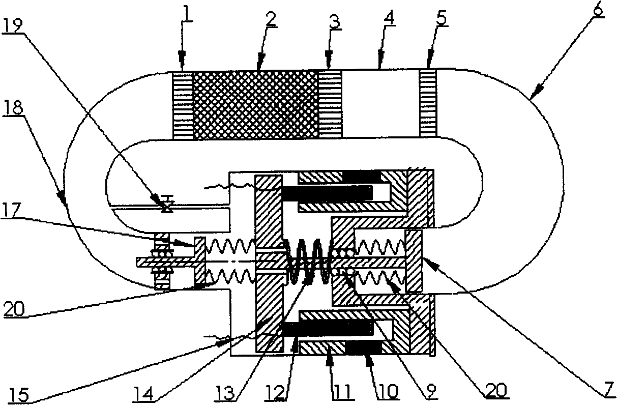
[0065] The structure of this embodiment is as image 3 Shown, it is transformed on the basis of embodiment 2. In this embodiment, the spring-piston assembly in Embodiment 2 is replaced by the bellows-mass assembly as the elastic-mass assembly of the generator, and the materials, manufacturing processes and connection methods of the remaining parts are the same as in Embodiment 2. The bellows-mass block assembly is composed of a metal bellows and a mass block, and the linear sliding bearing 9 is fixedly connected with the mass block to play a supporting role.
PUM
 Abstract
Description
Claims
Application Information