Electric current sensing method and device based on polarization degree demodulating

A technology for sensing devices and polarization degrees, applied in measuring devices, measuring light polarization, measuring current/voltage, etc., can solve problems such as cost reduction and interference, achieve great flexibility, mature materials and components, and benefit Promoted app performance

Inactive Publication Date: 2006-05-03
SHANGHAI INST OF OPTICS & FINE MECHANICS CHINESE ACAD OF SCI
View PDF0 Cites 13 Cited by
  • Summary
  • Abstract
  • Description
  • Claims
  • Application Information

AI Technical Summary

Problems solved by technology

[0007] The technical problem to be solved by the present invention is to overcome the deficiencies of the above-mentioned prior art and provide a current sensing method and device based on pola

Method used


Image

  • Electric current sensing method and device based on polarization degree demodulating
  • Electric current sensing method and device based on polarization degree demodulating
  • Electric current sensing method and device based on polarization degree demodulating

Examples


Embodiment 1

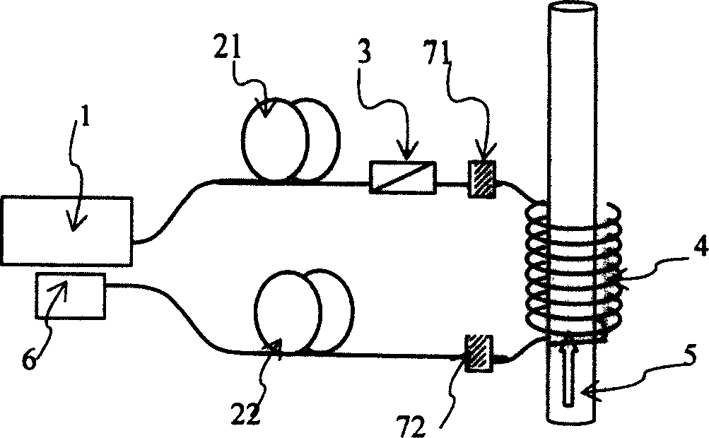
[0039] Embodiment 1: A scheme of using a fiber grating pair to form a fiber cavity, such as figure 2 shown. As can be seen from the figure, the current sensing device for demodulating the degree of polarization of the Faraday effect of the present invention is composed of an unpolarized light source 1, a first transmission fiber 21, a polarizer 3, a fiber cavity, and a second transmission fiber 22 connected in series in sequence. And light polarization analyzer 6 constitutes. Described optical fiber cavity is made of the first reflector 71, fiber ring 4, the second reflector 72 that are connected in series, and described fiber ring 4 is a multi-turn fiber ring that surrounds current cable 5 to be measured, and described first The reflectance values ​​of the first reflector 71 and the second reflector 72 are greater than 0 and less than 1.

[0040] The first reflector 71 and the second reflector 72 are the first fiber Bragg grating 73 and the second fiber Bragg grating 74 re...

Embodiment 2

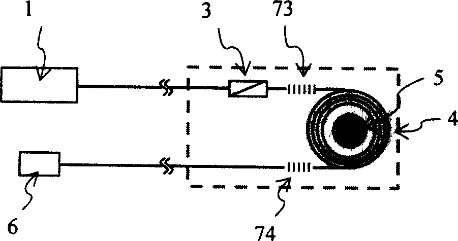
[0041] Embodiment 2: A solution for forming a fiber ring using a fiber coupler, such as image 3 shown.

[0042] 1, 3, 4, 5, 6, 21, and 22 in the figure are all connected with figure 1 same. However, instead of two separate reflectors 71, 72, one fiber optic coupler 75 is used. It can function as two reflectors. The fiber cavity is composed of a 2×2 fiber coupler 75 and a fiber ring 4: the output terminal of the polarizer 3 is connected to the first port a of the 2×2 fiber coupler 75, and the fiber coupler 75 is connected to the first port a. The second port b and the fourth port d are connected to both ends of the optical fiber ring 4 , and the third port c is connected to the second transmission optical fiber 22 . Assuming that the splitting ratio of the coupler is K%: (1-K)%, then, after the light is input from the first port a of the coupler, (1-K)% of the power is output from the third port c, and the remaining K % power is output from the fourth port d. This part o...

Embodiment 3

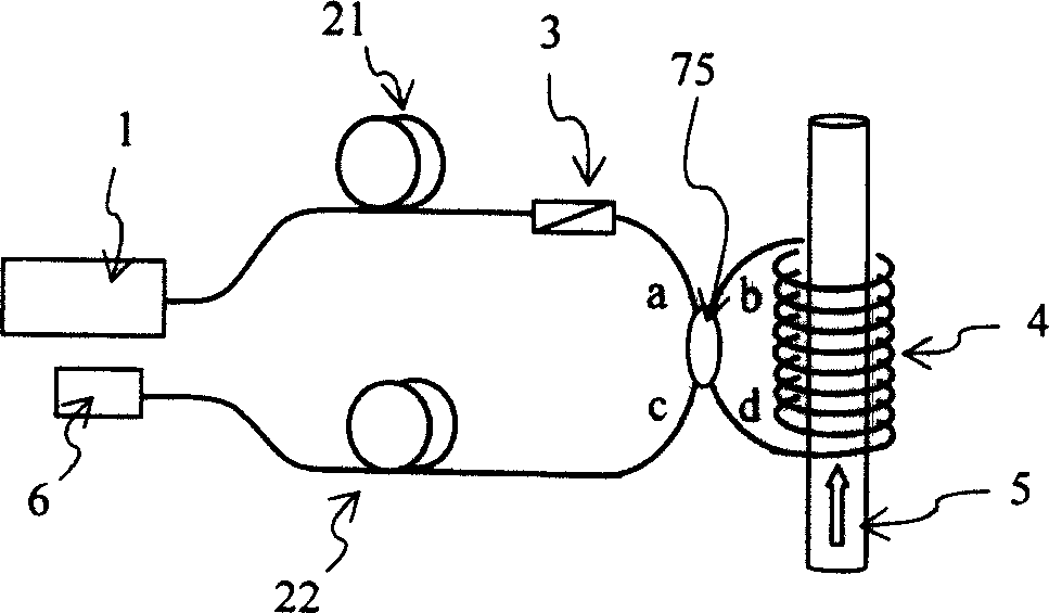
[0043] Embodiment 3: A scheme utilizing a fiber coupler and a Faraday rotating mirror, such as Figure 4 shown. Among the figure, each element such as 1, 21, 22, 3, 5, 6, 75 is all related to image 3 same. Described optical fiber cavity is formed by the first multi-turn optical fiber ring 41 and the second multi-turn optical fiber ring 42 two sections connected by the described fiber coupler 75: the first multi-turn optical fiber ring 41 and the second multi-turn optical fiber ring 42 One end is respectively connected to the second port b and the fourth port d of the fiber coupler 75, and the other ends of the first multi-turn optical fiber ring 41 and the second multi-turn optical fiber ring 42 are respectively connected to the first Faraday rotating mirror 81 and a second Faraday rotating mirror 82, the second transmission fiber 22 is directly connected to the third port c of the fiber coupler 75.

[0044] The incident light enters the sensor head through a circulator 9;...


PUM


Abstract

The invention relates to a polarization modulation current sensing method and apparatus based on Faraday Effect which is used in electricity measurement with high voltage and high current. The method is based on Faraday light polarization rotating effect, which rotates the multi-loop fiber optical inside the fiber optical chamber with multi-loop fiber optical ring on the wire or cable of the tested current so that a linearly-polarized light can through the fiber optical chamber and reflects many times; it changes the light wave of the single polarization side rotating angle into a superposition of a plurality of light wave of different polarization side rotating angle; the superposition light wave has special polarization which has the respondent relation with the current intensity of the multi-loop fiber optical ring.

Description

technical field [0001] The invention relates to the measurement of high voltage and strong current, in particular to a current sensing method and device based on Faraday effect-based polarization demodulation, which is mainly used in high voltage and strong current power sensing systems requiring insulation measurement. Background technique [0002] With the continuous expansion of the requirements for power development in industrial, military and civil applications, the installed capacity of the power industry continues to grow. How to measure high-voltage and strong electricity has become one of the problems that the power industry needs to solve urgently. [0003] Much research has been done on the current sensing needs of the power industry. Traditional power sensing is mainly based on the current transformer (CT) based on electromagnetic induction. However, the current transformer has problems such as insulation difficulty, high cost, magnetic saturation, and ferromagn...

Claims


Application Information

Patent Timeline
IPC IPC(8): G01R19/00G01J4/00
Inventor 刘峰方祖捷瞿荣辉叶青耿健新
Owner SHANGHAI INST OF OPTICS & FINE MECHANICS CHINESE ACAD OF SCI
Why Eureka
Try Eureka