Combustion unit for turbocharger

A turbocharger and combustion device technology, which is applied to combustion equipment, noise reduction devices, exhaust devices, etc., can solve the problems of not being able to improve the performance of internal combustion engines, etc.

Inactive Publication Date: 2006-05-03
PRODRIVE 2000
View PDF5 Cites 6 Cited by
  • Summary
  • Abstract
  • Description
  • Claims
  • Application Information

AI Technical Summary

Problems solved by technology

Such devices generally do not improve engine performance at low e

Method used


Image

  • Combustion unit for turbocharger
  • Combustion unit for turbocharger
  • Combustion unit for turbocharger

Examples


Embodiment Construction

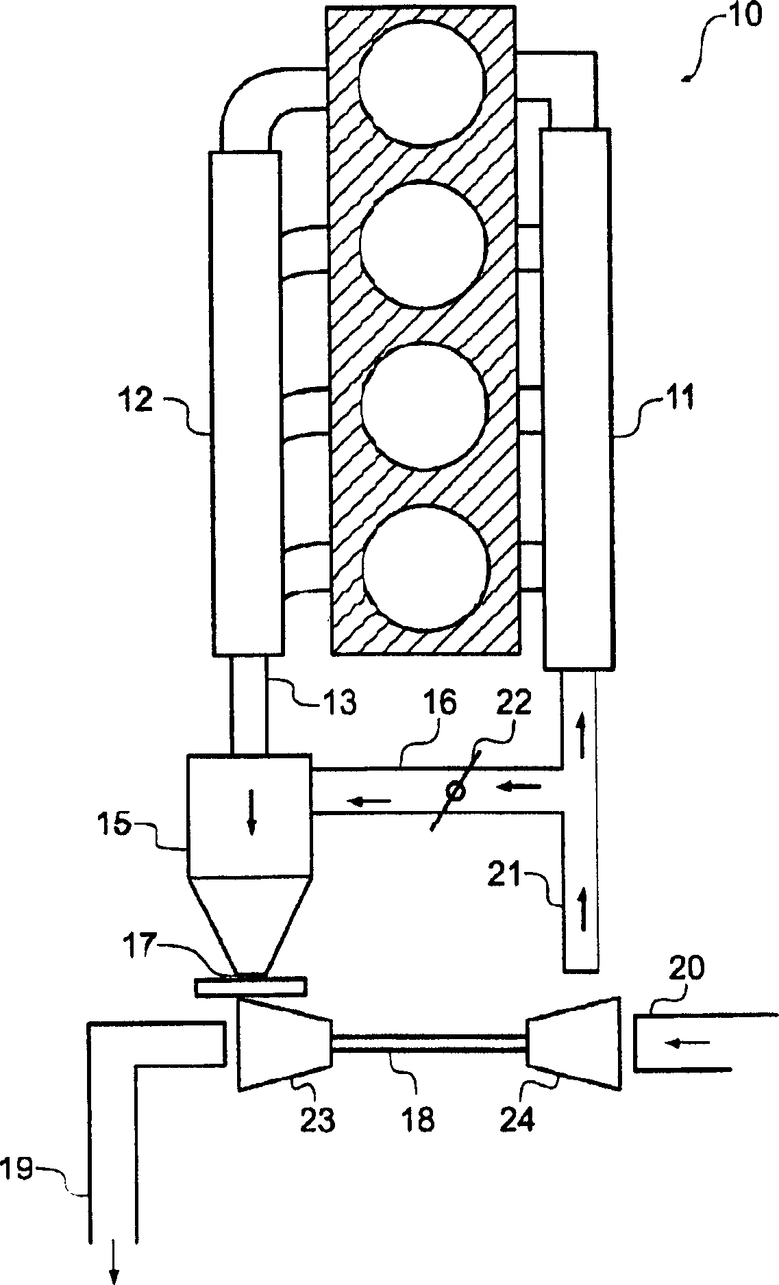
[0023] With reference to the accompanying drawings, first of all figure 1 , shows an internal combustion engine 10 which may be of any suitable form, in this case a four cylinder petrol engine, but which may also be a diesel or other internal combustion engine. The internal combustion engine 10 has: an intake manifold 11 through which air is introduced into a combustion chamber of the internal combustion engine 10; and an exhaust manifold 12 through which combustion products in the internal combustion engine 10 are collected and discharged to Exhaust outlet 13.

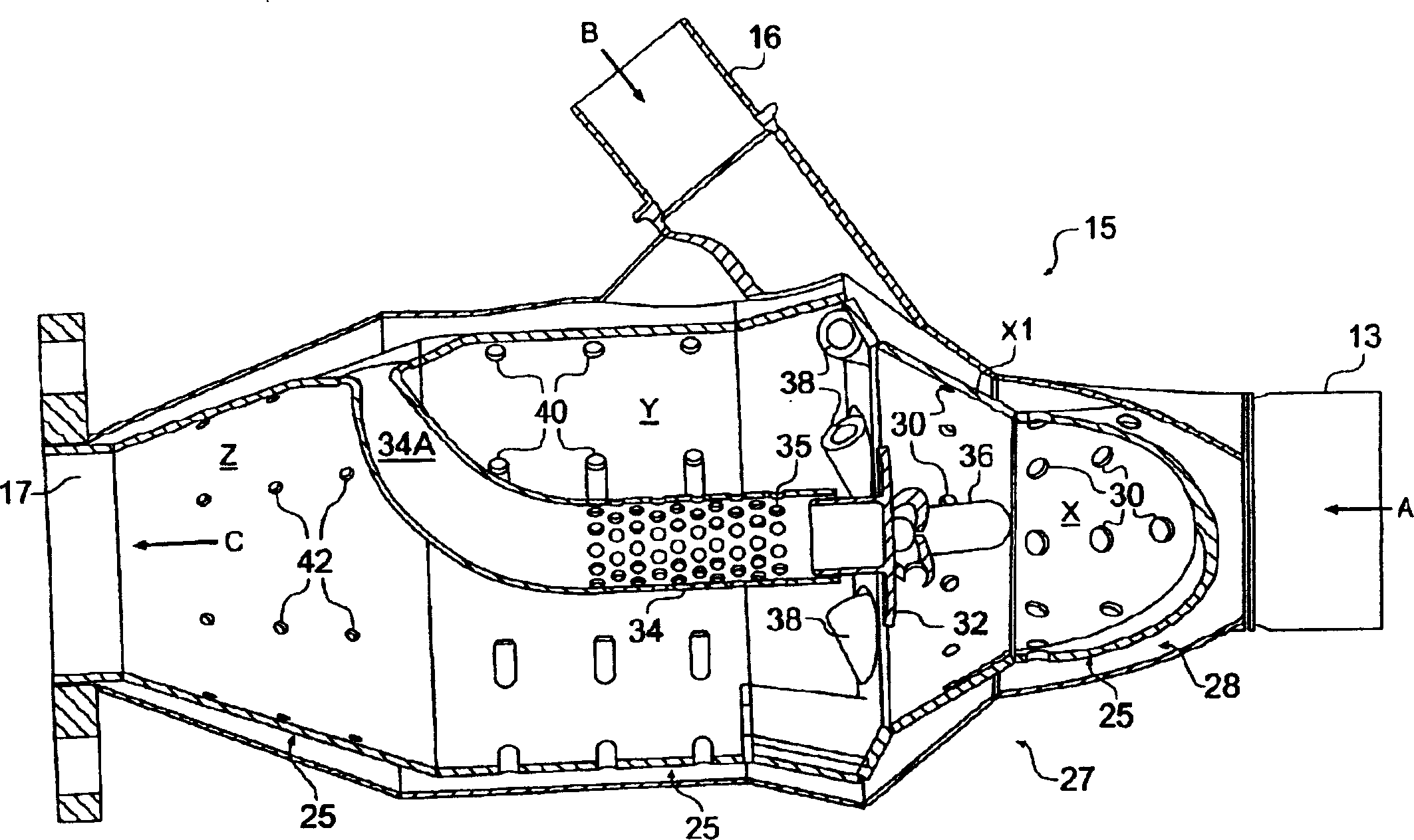
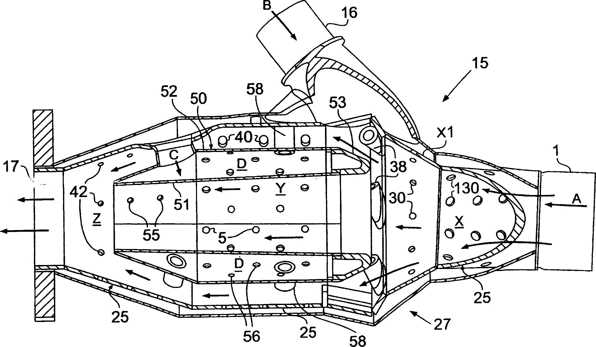
[0024] The combustion chamber 15 is supplied with exhaust gas from the internal combustion engine 10 and air from an inlet 16 and exhausts gases from an outlet 17 driving a turbine 23 of a turbocharger 18 . Gas is discharged from the turbine 23 to the exhaust pipe 19 , while the turbocharger 18 draws air compressed by the compressor 24 through the intake 20 and discharges it through the high pressure line 21 . The a...


PUM


Abstract

A combustion unit (15) is primarily intended to feed a turbocharger (18) to generate a compressed air supply to an internal combustion engine (10). The unit (15) is suppplied with exhaust gasses from the engine and these gases are mixed with air in the unit combust material in the exhaust gases and give and enhanced supply to the turbocharger. The combustion unit is generally cylindrical and air is added to the exhaust gases at the inlet (13) to promote combustion and the combustion gases pass at high speed through an annuler space towards an outlet (17) leading to the turbocharger (18).

Description

technical field [0001] The invention relates to a combustion device for a turbocharger, in particular a turbocharger for an internal combustion engine, an internal combustion engine comprising the combustion device, and a method of operating the internal combustion engine. Background technique [0002] Turbocharging devices are commonly used to push a flow of air into an internal combustion engine, thereby increasing the performance of the internal combustion engine. Such devices generally do not improve the performance of the internal combustion engine at low engine speeds and during transitions between fine throttle adjustments and full throttle adjustments of the internal combustion engine. [0003] From US 3849988 (French state (Etat Francais)), US 3736752 (French state), US 4026115 (French state), US 4009574 (French state) and GB 537483 (Napier (Napier)) known, provide a kind of Combustion chamber with separate fuel supply. Contents of the invention [0004] The obj...

Claims


Application Information

Patent Timeline
IPC IPC(8): F02B37/02F01N3/20F01N3/26F01N3/34F01N3/38F02B1/00F02B3/00F02B37/00F02B37/16F02B37/20F23C7/06
CPCF01N3/20F01N3/2033F01N3/26F01N3/34F01N3/38F01N2250/04F01N2270/04F01N2430/06F01N2470/02F01N2470/04F01N2470/08F02B1/00F02B3/00F02B37/00F02B37/02F02B37/166F02B37/20Y02T10/12
Inventor 罗兰·布罗德本特
Owner PRODRIVE 2000
Why Eureka
Try Eureka