Apparatus for changing capacity of multi-stage rotary compressor

A compressor capacity, compression chamber technology, applied in the direction of rotary piston machinery, pumping device components for elastic fluid, pump combination for elastic fluid rotary piston type/swing piston type, etc., can solve the installation space Not ideal, increased number of manufacturing processes, reduced reliability of compression units, etc.

Inactive Publication Date: 2006-05-10
LG ELECTRONICS INC
View PDF0 Cites 10 Cited by
  • Summary
  • Abstract
  • Description
  • Claims
  • Application Information

AI Technical Summary

Problems solved by technology

[0017] First of all, in saving mode, the method in which the blades are moved backwards and fixed has the problem that special parts such as parts etc. and the installation space of this part are not ideal and increase the number of manufacturing processes
[0018] Second, due to repeated collisions of parts with the blade, the surface of the blade may be damaged over time, and reliability problems such as abrasion, foreign matter generation, etc. may be caused
[0019] Third, since variable frequency motors are usually expensive, using variable frequency motors as drive units may cause an increase in manufacturing costs
[0020] Fourth, when using an existing con

Method used


Image

  • Apparatus for changing capacity of multi-stage rotary compressor
  • Apparatus for changing capacity of multi-stage rotary compressor
  • Apparatus for changing capacity of multi-stage rotary compressor

Examples


Embodiment Construction

[0034] Reference will now be made in detail to the preferred embodiments of the present invention, examples of which are illustrated in the accompanying drawings. The same reference numerals refer to the same components as in the conventional art.

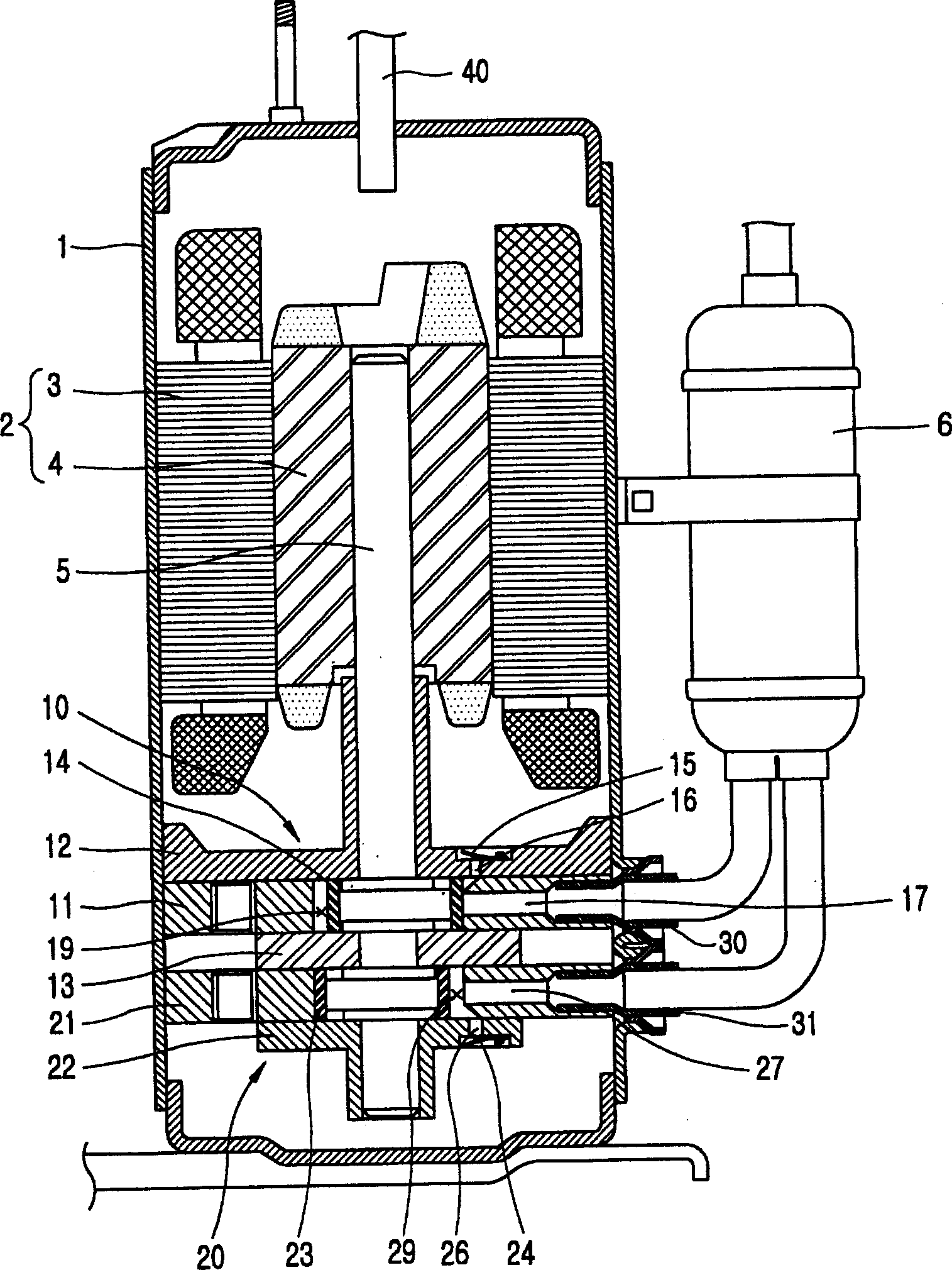
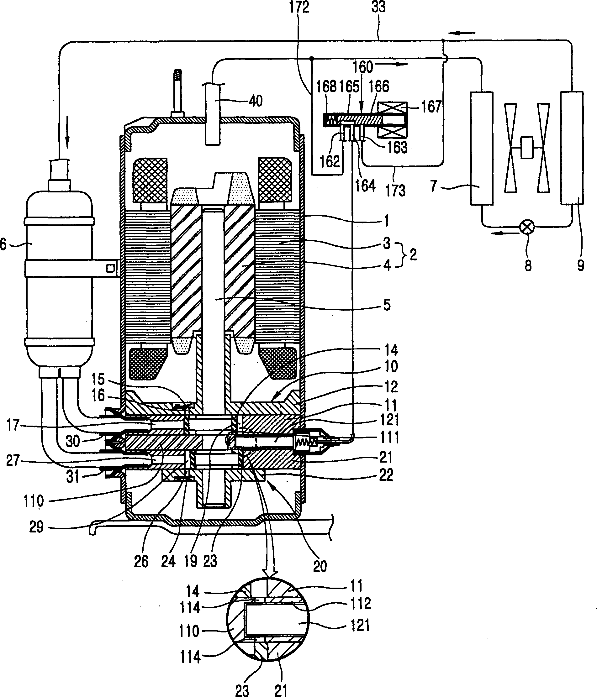
[0035] figure 2 A cross-sectional view of a multi-stage rotary compressor according to a first embodiment of the present invention is shown.

[0036] As shown in the figure, the multi-stage rotary compressor according to the present invention includes: a casing 1 equipped with a plurality of suction pipes 30 and 31 communicating with each other and a discharge pipe 40; A motor unit 2 generating a rotational force; a first compression unit 10 and a second compression unit 20 mounted on the lower side of the housing 1 in a multi-stage manner, for receiving the rotational force generated by the motor unit 2 through the rotating shaft 5 respectively compressing refrigerant; a first slide valve 121 selectively communicating with the ...


PUM


Abstract

A device for changing the capacity of a multi-stage compressor, comprising: a first cylinder provided with a first suction port and a first discharge port, the first cylinder moves linearly with a first orbiting rolling piston and a first The first vane contacted by a rolling piston is divided into a first suction chamber and a first compression chamber; a second cylinder with a second suction port and a second discharge port is formed by a second rolling piston orbiting and a straight line The second vane moving and in contact with the second rolling piston is divided into a second suction chamber and a second compression chamber; an intermediate bearing inserted between the first cylinder and the second cylinder has the a bypass hole communicating between the compression chambers, and the intermediate bearing has a valve hole for communicating with the middle of the bypass hole; a slide valve slidably connected to the valve hole of the intermediate bearing, which can selectively open or close the bypass hole; And the pressure switch unit for selectively sending the discharge pressure to one side of the spool valve, so it is possible to change the capacity using all of the multiple compression units, and the energy saving effect suitable for the saving mode can be obtained.

Description

technical field [0001] The present invention relates to a rotary compressor performing multi-stage compression, and more particularly to a multi-stage rotary compressor capable of using all compression units to achieve optimum compression efficiency. Background technique [0002] A compressor is a device that receives energy from an energy generator such as an electric motor to compress air, refrigerant gas, or other specialized gas to increase pressure and is widely used in industry. Depending on how compression is performed, compressors can be classified into positive displacement compressors and turbo compressors. Positive displacement compressors perform compression by a compression method in which pressure is increased by volume reduction; and turbo compressors perform compression by converting kinetic energy of gas into pressure energy. [0003] A rotary compressor, which is a type of positive displacement compressor, is generally used in an air conditioning apparatus...

Claims


Application Information

Patent Timeline
IPC IPC(8): F04C28/00F04C23/00
CPCF04C18/356F04C23/001F04C28/18F04C28/26F04C29/124F04C2210/26F04C2240/40F16F1/04Y10S415/00Y10S417/00
Inventor 黄善雄
Owner LG ELECTRONICS INC
Why Eureka
Try Eureka