Bottom-expanding equipment for pipeline sinking precast reinforced concrete pile

A technology of expanding bottom piles and equipment, which is applied in the direction of drilling equipment, drilling equipment and methods, sheet pile walls, etc., which can solve the problems of poor accuracy, unsuitable excavation needs, low effect and control ability, etc., and achieve simple operation Convenience, good soil crushing effect, and strong equipment controllability

Inactive Publication Date: 2006-05-24
王国奋
View PDF0 Cites 9 Cited by
  • Summary
  • Abstract
  • Description
  • Claims
  • Application Information

AI Technical Summary

Problems solved by technology

[0002] With the rapid development of the construction industry, high-rise buildings in large and medium-sized cities can be seen everywhere, and high-rise buildings have more and more requirements on their foundation bearing capacity. In order to increase the bearing capacity of single piles, expansion piles are often used to reduce the foundation piles Distribution density and cost reduction, followed by bottom expansion excavation equipment came into being, but despite this, the previous bottom expansion excavation equipment is not suitable for the excavation needs of immersed tube prefabricated steel concrete bottom expansion, because the equipment is not positioned in the submerged Instead of placing it on the bottom soil, its accuracy is poor, its effect and control ability are low, so its popularization and application are limited to a certain extent.

Method used


Image

  • Bottom-expanding equipment for pipeline sinking precast reinforced concrete pile
  • Bottom-expanding equipment for pipeline sinking precast reinforced concrete pile
  • Bottom-expanding equipment for pipeline sinking precast reinforced concrete pile

Examples


Embodiment 1

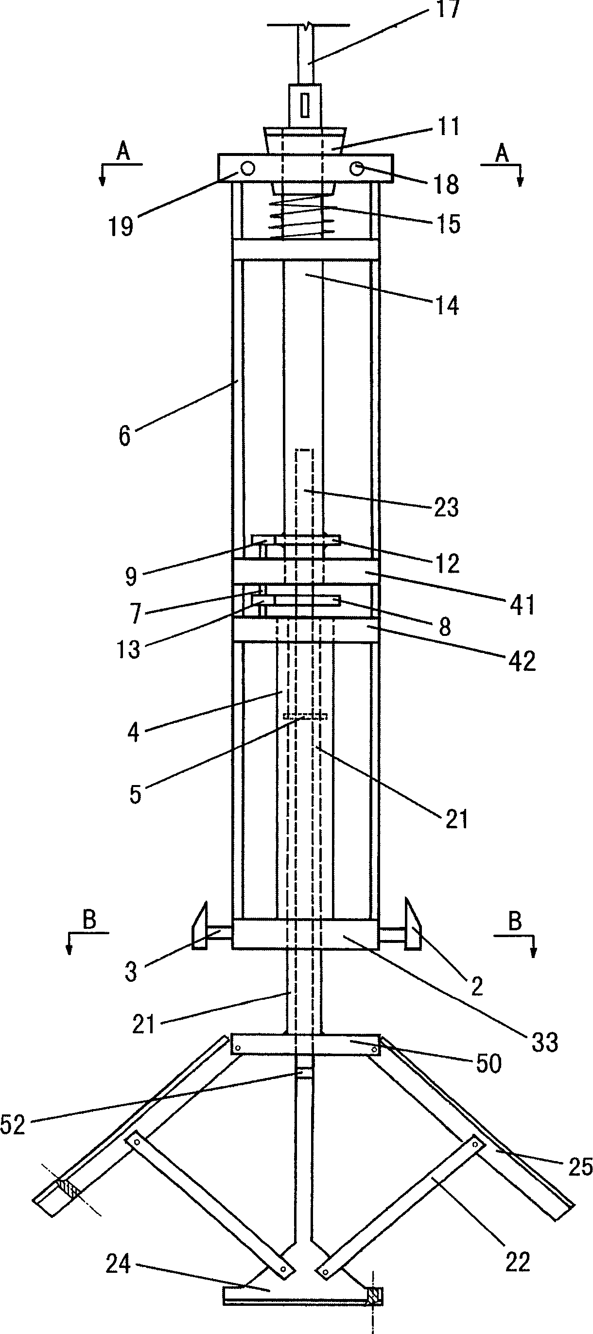
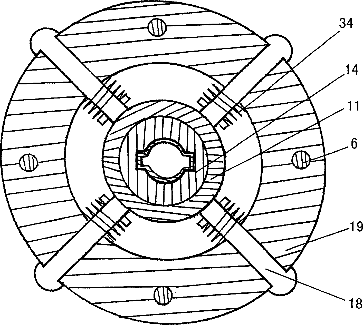
[0021] Embodiment one: if figure 1 Shown is the front view structure schematic diagram of the present invention. The upper fixed plate 19 and the lower fixed plate 33 of the frame are connected into one body by four or two or eight or more columns 6 uniformly distributed along the circumferential direction between the two, and the top and the middle are also provided with at least two Block strengthens fixed plate 41,42, and the metal plug 11 that is conical cone shape is sleeved on the upper end of last axle sleeve 14, and places the center of last fixed disk 19, and the lower side is provided with support spring 15, and the upper end of upper axle sleeve 14 and The power rod 17 connected to the power source is connected, the lower end of the upper shaft sleeve 14 is placed on the lower plate of the reinforced fixed plate 41, and a rolling bearing is arranged outside it, and the upper end of the gear 12 is fixed on the lower part of the upper shaft sleeve. In the shaft sleev...

Embodiment 2

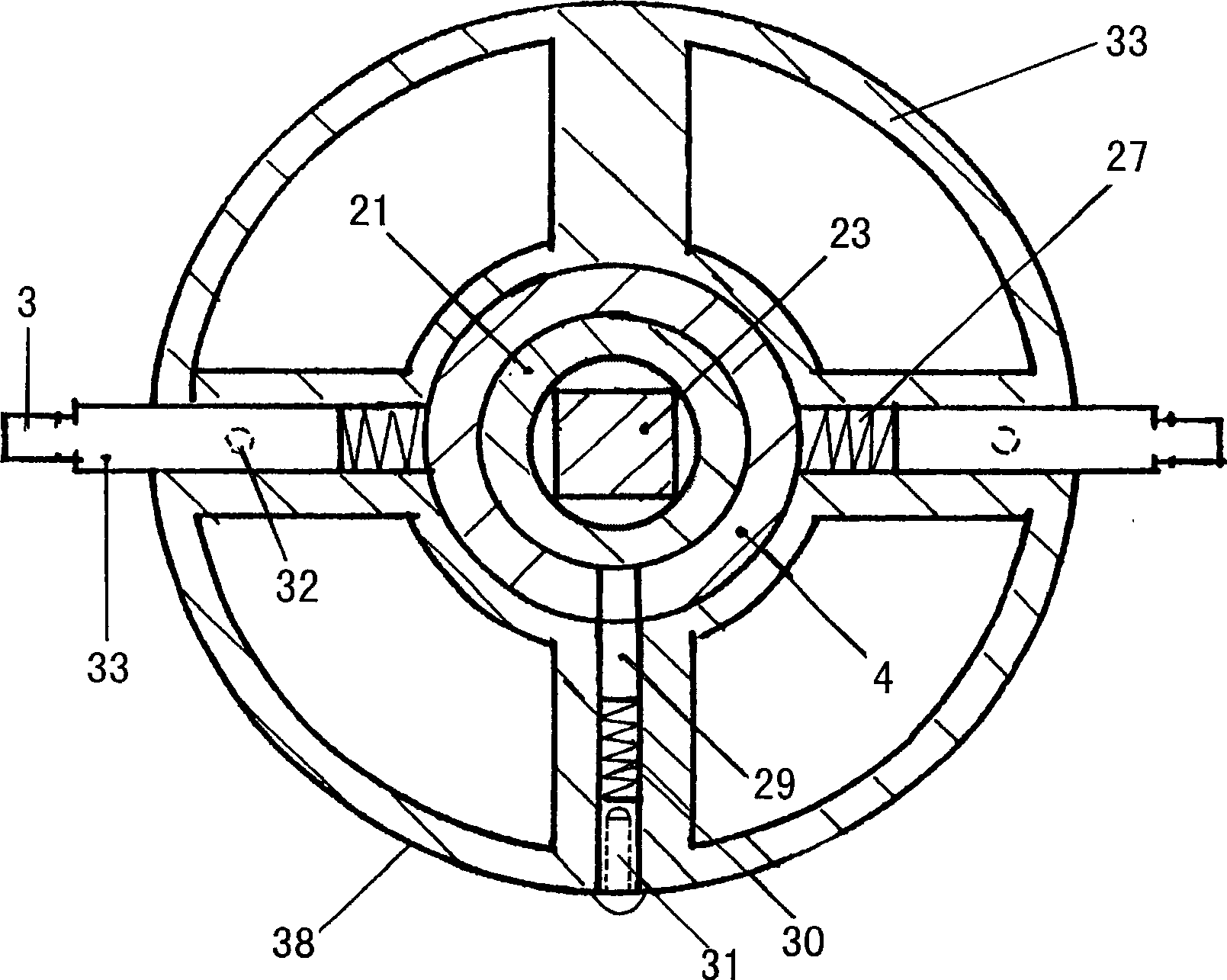
[0023] Embodiment 2: The transmission mechanism described in Embodiment 1 can also adopt the following structure: it includes a power rod with one end connected to the power source and the other end connected to the upper shaft sleeve 14, the gear 12 fixed on the lower part of the upper shaft sleeve 14 and The pinion 9 located at the upper end of the gear shaft 7 meshes, the pinion 13 at the lower end of the shaft meshes with the gear 8 on the central shaft 23, and the lower end of the central shaft 23 passes through the frame, the lower fixed plate 33, the tool holder horizontal The bar 50 is connected to the upper end of the vertical cutting knife 24, and its cross section is a circle below the upper circle or a circle with a missing edge. That is to drive the knife rest cross bar 50 with the central axis 23, and the knife rest cross bar 50 drives the lower axle sleeve 21. Other structures are the same as in Embodiment 1.

Embodiment 3

[0024] Embodiment 3: The gear shaft 7, gear 8, gear 12 and pinion 13 described in Embodiment 1 and Embodiment 2 can be replaced by a fixed gear 8, and the gear 8 is screwed to the central shaft 23, and other structures are implemented in the same way example one.


PUM


Abstract

This invention discloses a under-reamed pile equipment for foundation construction, especially the equipment for immersed tube fabricated steel-concrete under-reamed pile. It includes frame positioned with immersed tube, power source, driving mechanism and cutting rest. Compared with current technology, said invention has advantages of precision positioning, high single pile load bearing ability, convenient operation, high efficiency and engineering quality.

Description

technical field [0001] The invention relates to a bottom expansion pile equipment for foundation construction, in particular to a bottom expansion equipment for immersed tube prefabricated steel concrete bottom expansion piles, which is the first choice equipment for bottom expansion and crushing of immersed tube prefabricated steel concrete bottom expansion piles. Background technique [0002] With the rapid development of the construction industry, high-rise buildings in large and medium-sized cities can be seen everywhere, and high-rise buildings have more and more requirements for their foundation bearing capacity. In order to increase the bearing capacity of single piles, expansion piles are often used to reduce the foundation pile Distribution density and cost reduction, followed by bottom expansion excavation equipment came into being, but despite this, the previous bottom expansion excavation equipment is not suitable for the excavation needs of immersed tube prefabri...

Claims


Application Information

Patent Timeline
Patent Type & Authority Applications(China)
IPC IPC(8): E02D5/44E21B7/28
Inventor 王国奋
Owner 王国奋
Why Eureka
Try Eureka