High-pressure device for crystal growth
A high-pressure device, a technology for growing crystals, applied in the process of applying ultra-high pressure and other directions, can solve problems such as the danger of gas pressure vessels
- Summary
- Abstract
- Description
- Claims
- Application Information
AI Technical Summary
Problems solved by technology
Method used
Image

Examples
example 1
[0069] Example 1 - Chamber of prior art
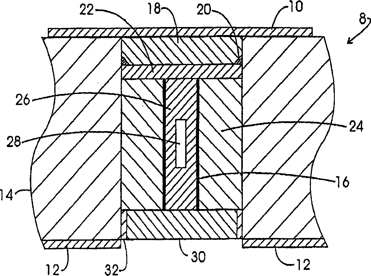
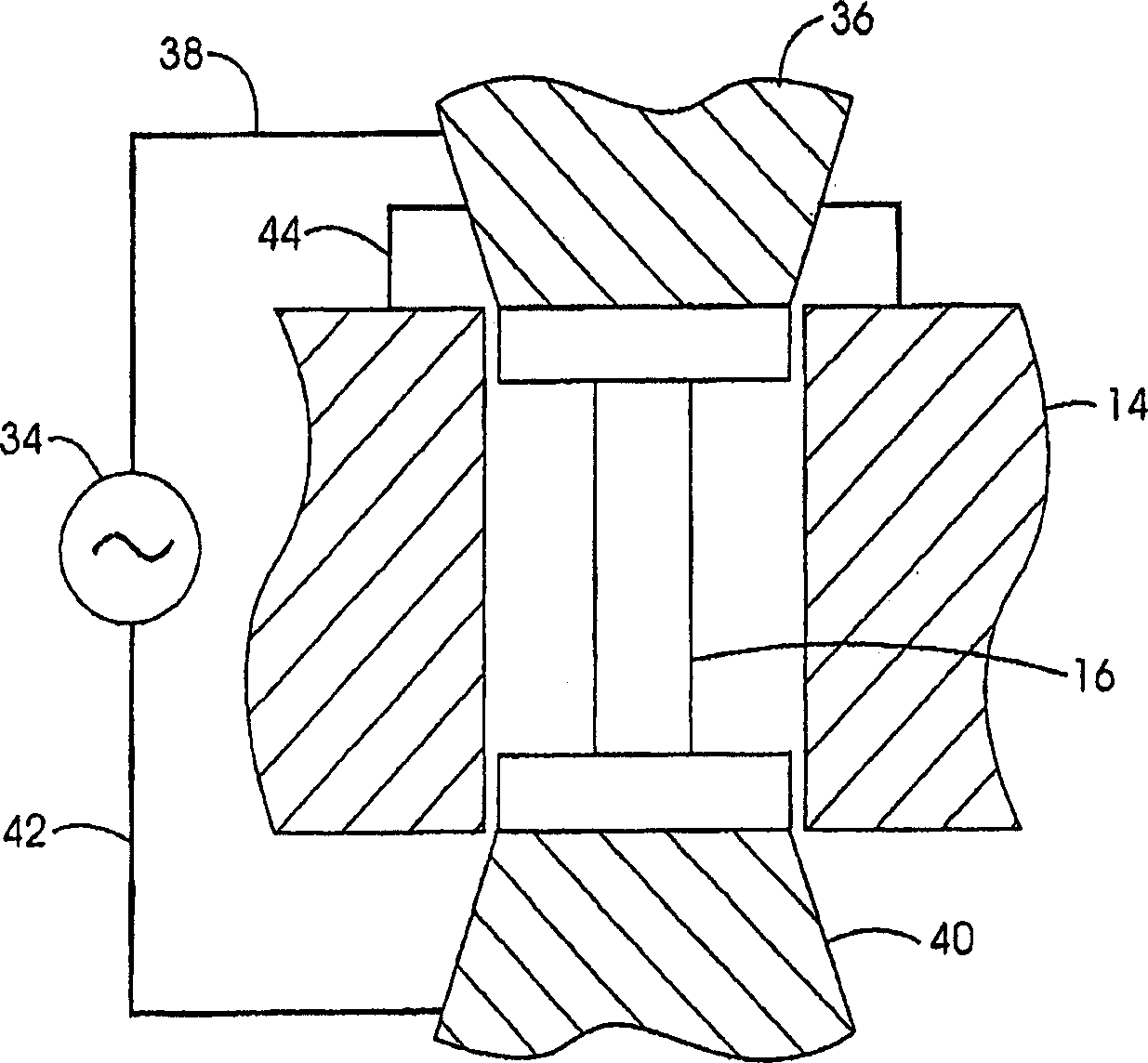
[0070] As described in U.S. Patent Application Publication No. 2003 / 0141301, a 0.5-inch-diameter silver airtight chamber is filled with polycrystalline gallium nitride (three seeds, each weighing 3-4 mg), ammonium fluoride, and ammonia, and sealed. . As described in US Patent Application Publication No. 2003 / 0140845 and shown in Figures 1 and 2, a sealed airtight chamber is placed in a chamber in a zero-shock HP / HT device.
[0071] At the bottom of the chamber, the airtight compartment is isolated from steel end caps by sodium chloride plugs with a height of 0.934 inches. At the top of the chamber, the airtight compartment is insulated from steel end caps by a sodium chloride plug with a height of 0.624 inches. The end caps are cooled by heat conduction to the water-cooled anvil, so the top of the vessel is cooler than the bottom of the vessel during HP / HT operation due to the thinner NaCl insulation.
[0072] The airlock can be h...
example 2
[0076] Example 2 - Device of the invention
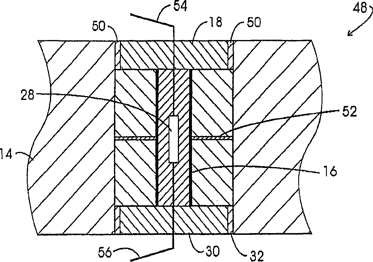
[0077] As in Example 1, a silver airlock was filled with polycrystalline gallium nitride, a seed crystal, ammonium fluoride, and ammonia and placed in a chamber. However, if image 3 As shown, in addition to having a graphite heating element extending from the top to the bottom of the chamber, an annular graphite disk is located at the vertical midpoint of the chamber with its inner diameter in contact with the heating element and its outer diameter in contact with the mold wall.
[0078] Such as Figure 15 As shown, the airtight chamber is heated from room temperature to about 700°C by passing electric current through the graphite tube heater. As in Example 1, the amount by which the top of the airlock is cooler than the bottom of the airlock is approximately proportional to the difference between the average temperature of the airlock and room temperature.
[0079] Once the bottom temperature reaches 700°C, current flows throu...
PUM
 Abstract
Description
Claims
Application Information
 - R&D
- Intellectual Property
- Life Sciences
- Materials
- Tech Scout
- Unparalleled Data Quality
- Higher Quality Content
- 60% Fewer Hallucinations
Browse by: Latest US Patents, China's latest patents, Technical Efficacy Thesaurus, Application Domain, Technology Topic, Popular Technical Reports.
© 2025 PatSnap. All rights reserved.Legal|Privacy policy|Modern Slavery Act Transparency Statement|Sitemap|About US| Contact US: help@patsnap.com