Exhaust emission control device of internal combustion engine

A control device and exhaust emission technology, applied in electrical control, exhaust device, engine control and other directions, can solve problems such as full opening

Inactive Publication Date: 2006-05-31
MITSUBISHI MOTORS CORP
View PDF1 Cites 8 Cited by
  • Summary
  • Abstract
  • Description
  • Claims
  • Application Information

AI Technical Summary

Problems solved by technology

[0005] However, the above-mentioned temperature raising method has the following disadvantages: for example, if the engine returns to normal control because the car decelerates during the temperature raising (that is, if the temperature rais

Method used


Image

  • Exhaust emission control device of internal combustion engine
  • Exhaust emission control device of internal combustion engine
  • Exhaust emission control device of internal combustion engine

Examples


Embodiment

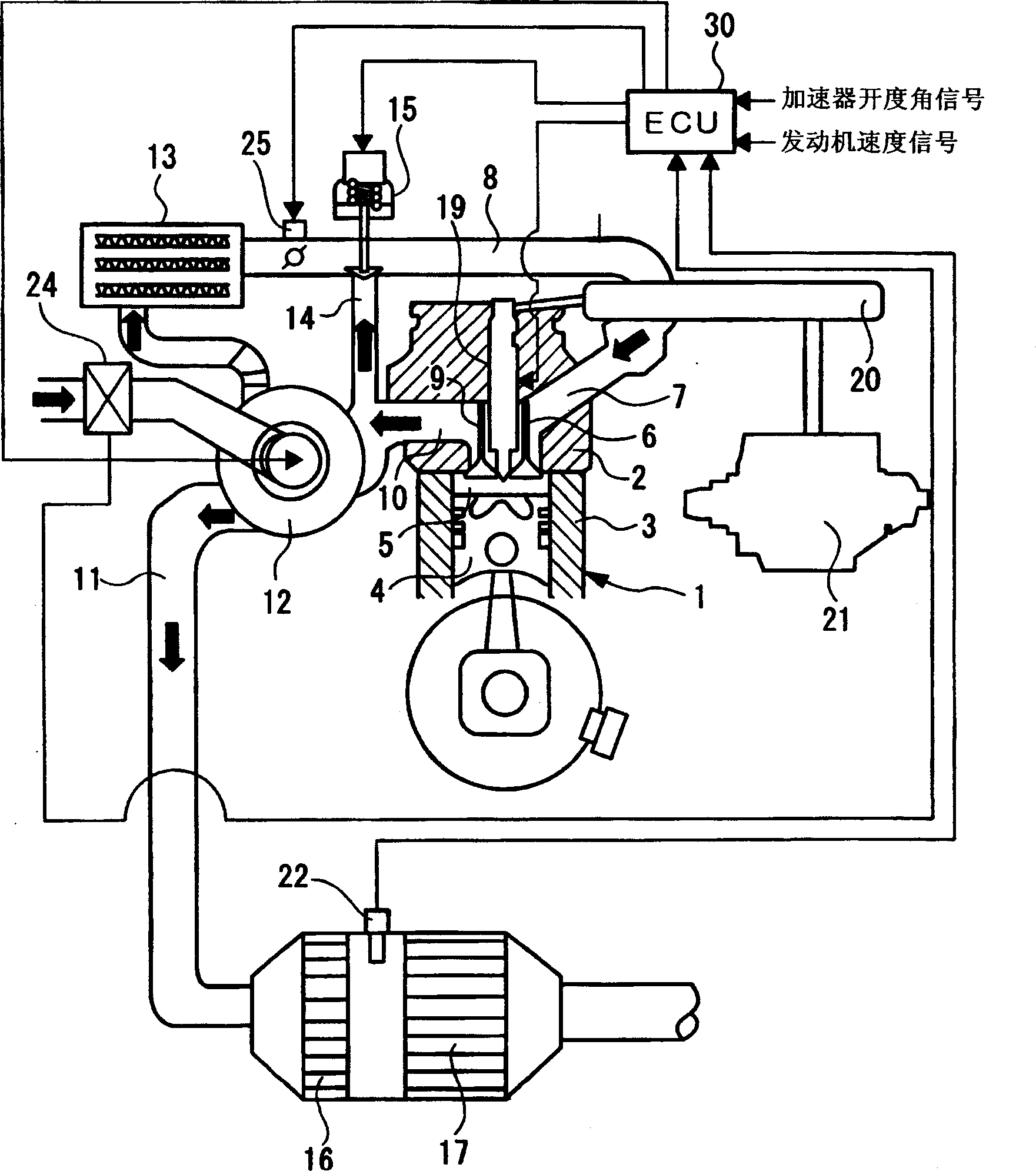
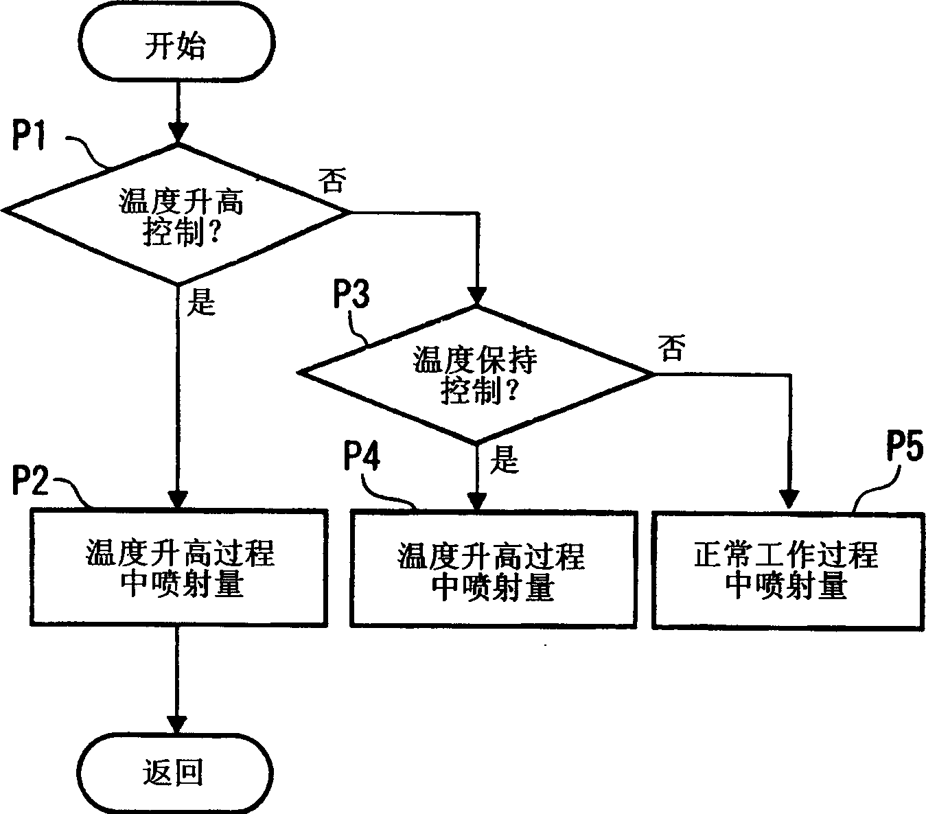
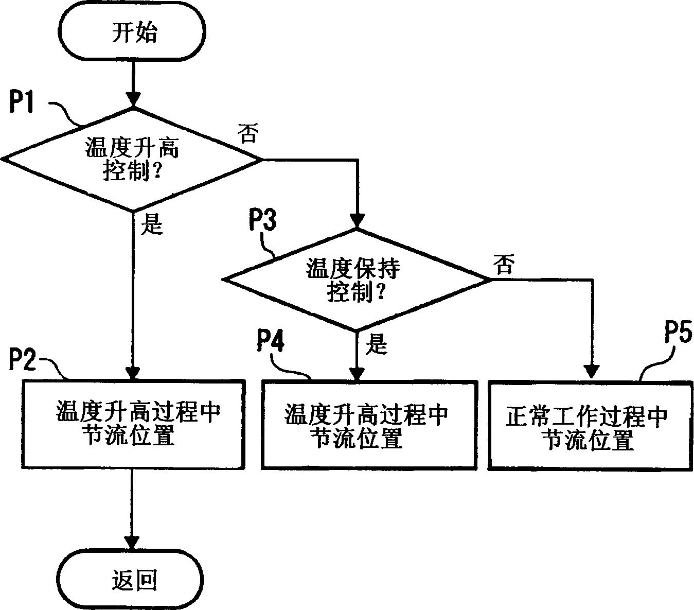
[0030] figure 1 is a schematic structural view showing a diesel engine exhaust emission control device according to an embodiment of the present invention. figure 2 is a flow chart of post-injection control. image 3 Is the flow chart of throttle valve control. Figure 4 It is a time table showing the relationship among DPF temperature, engine speed, throttle valve opening angle, accelerator opening angle, temperature maintenance control flag, and regeneration control flag. Figure 5(a) and 5(b) is a graph showing the effect of temperature maintenance control.

[0031] like figure 1 As shown, a multi-cylinder diesel engine (hereinafter referred to as an engine) 1 has a cylinder head 2 and a cylinder block 3 . A piston 4 is accommodated in the bore of each cylinder block 3 so that it can move in a reciprocating manner. The combustion chamber 5 is formed by the top surface of the piston, the wall surface of the cylinder bore, and the lower surface of the cylinder head.

...


PUM


Abstract

An exhaust gas emission control device of an internal combustion engine, comprises: DPF (17) provided in an exhaust passage (11) of the diesel engine (1) ; a throttle valve (25) for regulating the volume of intake air into the diesel engine (1) ; temperature raise control means (30) for performing restriction of intake air or post-injection or exhaust-stroke injection in order to raise the temperature of the DPF (17); and ECU (30) for controlling the throttle valve (25) in accordance with the operating state of the diesel engine (1). The ECU (30) controls the throttle valve (25) in order to retain the temperature of the DPF (17) by restriction of intake air when interrupting temperature raise control during temperature raise of the DPF (17).

Description

technical field [0001] The present invention relates to an internal combustion engine (hereinafter referred to as engine) exhaust emission control device, more specifically, relates to a diesel particulate filter or NO X An exhaust emission control device that adsorbs a catalyst. Background technique [0002] The exhaust gas from the diesel engine contains such as hydrocarbons (HC), carbon hydroxides (CO), nitrogen oxides (NO X ) and particulate matter (PM; hereinafter referred to as particles) pollutants. In order to suppress the pollution of these substances to the air, combustion technologies such as exhaust gas recirculation (hereinafter referred to as EGR) and common rail type high-pressure fuel injection, or the use of diesel oxidation catalyst (hereinafter referred to as DOC), diesel particulate filter (hereinafter referred to as DPF) and NO X Adsorption catalyst (lean NO X trap; hereinafter referred to as LNT) post-processing tec...

Claims


Application Information

Patent Timeline
IPC IPC(8): F01N3/02F01N3/24F01N3/28
CPCF02D41/0002F02D41/024F02D41/405Y02T10/12
Inventor 仓田和朗饭塚章近藤浩司信原惠
Owner MITSUBISHI MOTORS CORP
Why Eureka
Try Eureka