
Polygon mirror drive motor and laser mirror radiation device

A technology for driving motors and polygonal mirrors, applied in electromechanical devices, optics, electrical components, etc., can solve problems such as difficulty in correct measurement, adverse effects of installation errors, and reduced detection accuracy, to prevent the decline of detection accuracy and prevent laser light. Effect of Variation in Irradiation Interval

Inactive Publication Date: 2006-06-07
SANKYO SEIKI MFG CO LTD
View PDF1 Cites 6 Cited by
  • Summary
  • Abstract
  • Description
  • Claims
  • Application Information

AI Technical Summary

Problems solved by technology

[0011] However, there is a problem that the above-mentioned synchronization signal is easily affected by an installation error when installing the sensor 107.
[0012] That is to say, there is a problem that although the synchronous signal is detected by the sensor 107, when the sensor 107 is installed in the housing, there is a problem that it is not connected with the motor drive magnet that is arranged on the peripheral surface of the polygon mirror drive motor 103. In the positional relationship, when there is a deviation from the predetermined position, for example, when a synchronous signal with a different pulse width is detected, the synchronous signal itself will deviate, reducing the detection accuracy
[0013] In addition, the reduction of the detection accuracy is caused not only by installation errors when installing the sensor 107, but also by various errors, such as installation errors of the housing where the sensor 107 is installed, and installation errors when the motor drive magnet is fixedly installed. , the installation error of each component, the relative error between the mirror and the magnet, etc.
[0014] In this way, in the conventional polygon mirror driving motor in which the synchronization signal is individually detected by the sensor 107, the above-mentioned error causes a decrease in detection accuracy, and as a result, the laser irradiation interval of each reflection surface of the polygon mirror varies.
When the laser irradiation interval deviates, for example, if the laser mirror irradiation device is a laser printer, it becomes difficult to print correctly without confusion, and when the laser mirror irradiation device is a workshop measurement device, accurate measurement becomes difficulty

Method used


Image

  • Polygon mirror drive motor and laser mirror radiation device
  • Polygon mirror drive motor and laser mirror radiation device
  • Polygon mirror drive motor and laser mirror radiation device

Examples


Embodiment Construction

[0061] Next, the best mode for carrying out the present invention will be described with reference to the drawings.

[0062] [mechanical configuration]

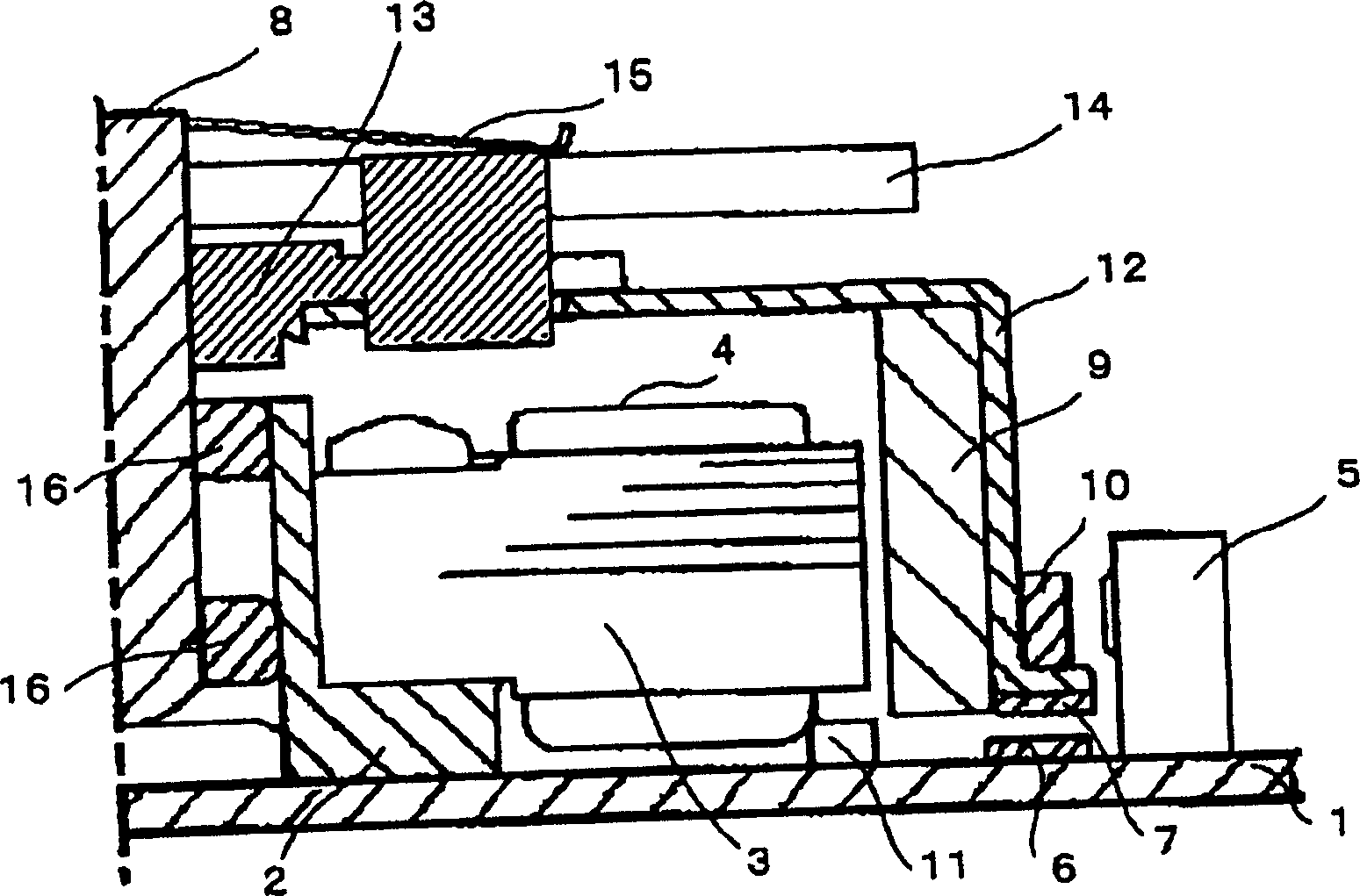
[0063] figure 1 It is a cross-sectional view of a polygon mirror driving motor according to an embodiment of the present invention. figure 1 For the sake of convenience, only the right half of the rotating shaft 8 is shown.

[0064] figure 1 A bearing housing 2 with a substantially cylindrical flange is mounted on the middle base plate 1 . A plurality of salient pole stator cores 3 are embedded on the outer peripheral side of the bearing seat 2 , and the stator iron cores 3 and the bearing seat 2 are fixed on the base plate 1 . The salient poles of the stator core 3 are wound with drive coils 4 for energization control.

[0065] Two bearings 16 are embedded in the inner peripheral side of the bearing housing 2, and are rotatably supported. The upper end of the rotating shaft 8 protruding from the bearing seat 2 and t...


PUM


Abstract

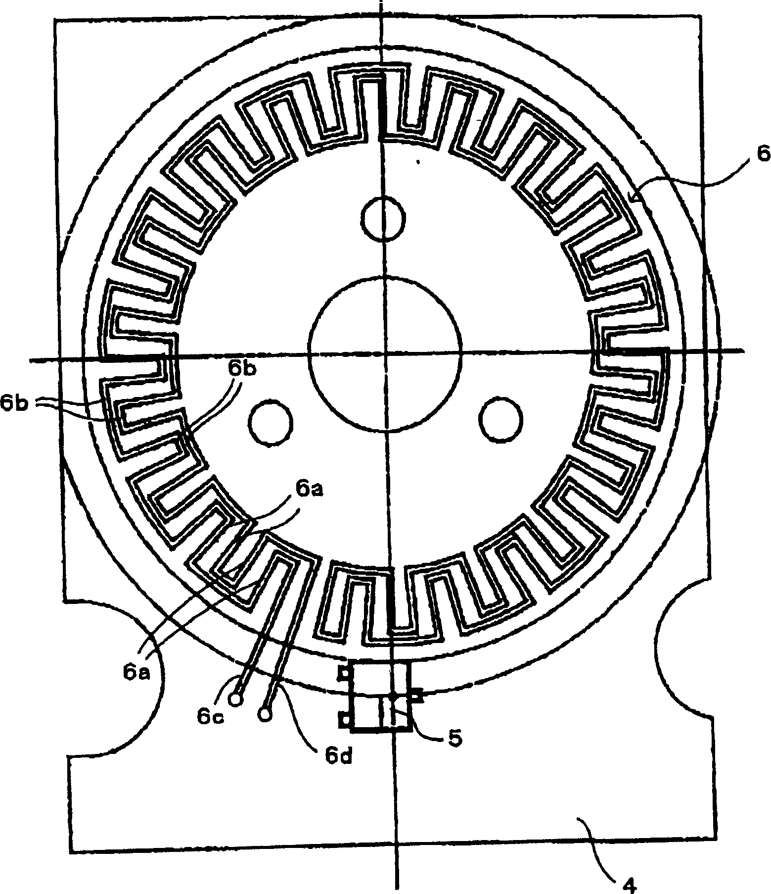
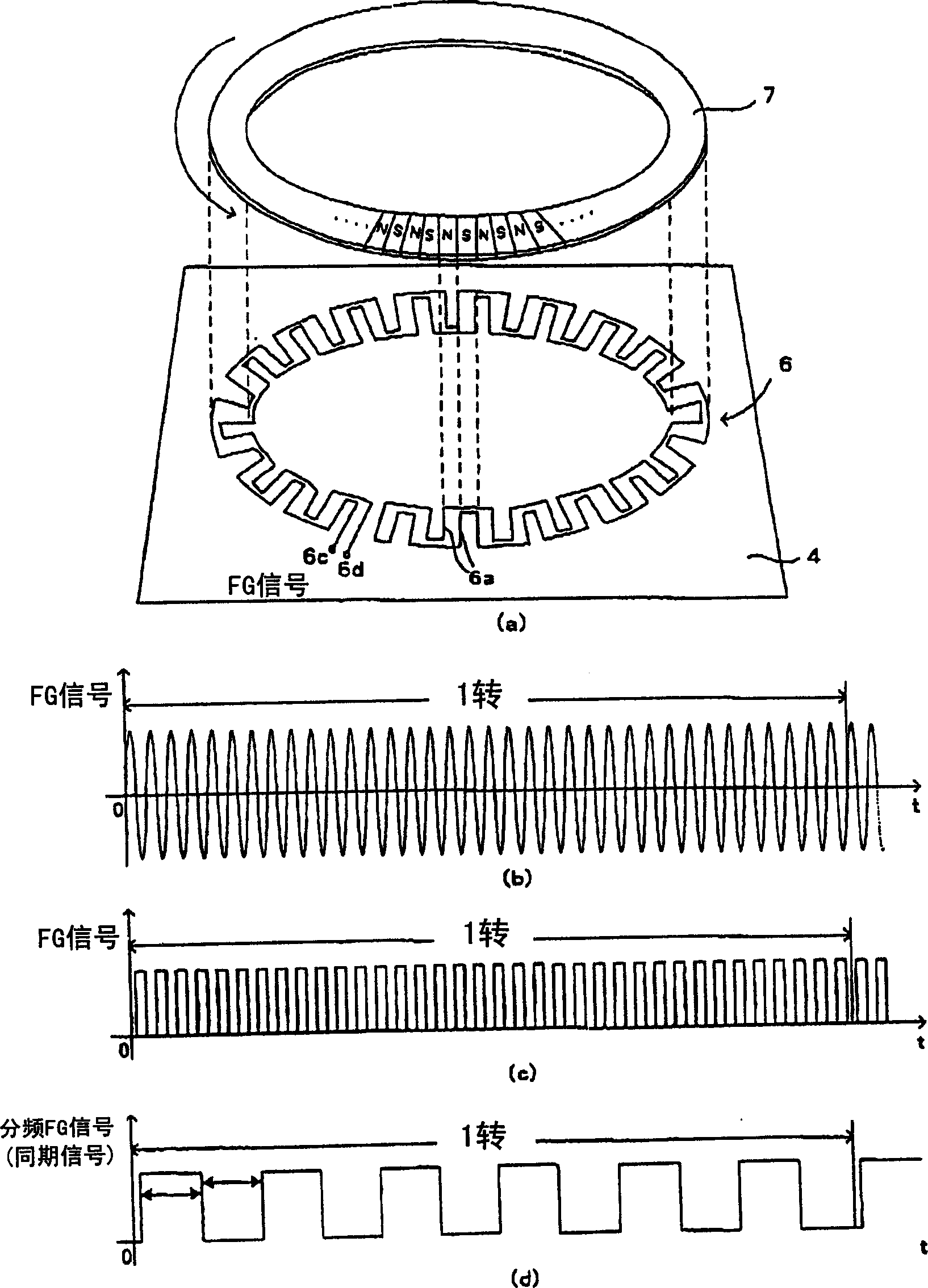
The invention discloses a polygonal mirror driving motor and a laser mirror irradiation device equipped with the polygonal mirror driving motor, which can prevent the deviation of the synchronization signal itself from reducing the detection accuracy caused by the installation error of various components, and then can accurately detect and control from A signal for the emission timing of the laser beam emitted from the laser light source. It is characterized by setting a frequency generating magnetizing part (FG magnet 7), a frequency generating pattern (FG pattern 6), and a frequency dividing circuit 24, and using the frequency dividing circuit 24 to generate frequency when the frequency generating magnetizing part (FG magnet 7) rotates The signal detected in the pattern (FG pattern 6 ) is frequency-divided into the number of mirror surfaces of the polygon mirror 14 and output.

Description

technical field [0001] The present invention relates to a polygon mirror drive motor that rotates and periodically deflects a laser beam emitted from a laser light source, and a laser mirror irradiation device equipped with the polygon mirror drive motor, and particularly relates to the control of the emission timing of the laser beam emitted from a laser light source . Background technique [0002] Generally, in laser printers, copiers, workshop measurement devices, etc., laser mirror irradiation devices with polygonal mirrors (rotating polygonal mirrors) are used in various places. For example, in the laser printer shown in the schematic diagram of FIG. 10 , the output beam of the semiconductor laser is parallelized by the imaging lens 102 and then enters the polygon mirror 104 that is rotated by a polygon mirror driving motor. Then, the reflected light from the polygon mirror 104 passes through the fθ lens, forms an image on the light spot on the photosensitive drum 106,...

Claims


Application Information

Patent Timeline
Patent Type & Authority Applications(China)
IPC IPC(8): H02K29/00B41J2/44G02B26/10H02K29/06
CPCG02B26/121
Inventor 栗田幸信
Owner SANKYO SEIKI MFG CO LTD
Learn More