Double side display organic electroluminescence light emitting device
An electroluminescent device and double-sided display technology, which is applied in the direction of electroluminescent light source, electric light source, lighting device, etc., can solve the problems of double-sided display device structure complexity, increased thickness and weight, and increased cost, and achieve structural Simple, low manufacturing cost, cost reduction effect
- Summary
- Abstract
- Description
- Claims
- Application Information
AI Technical Summary
Problems solved by technology
Method used
Image

Examples
Embodiment Construction
[0020] The present invention will be described in detail below in conjunction with the accompanying drawings.
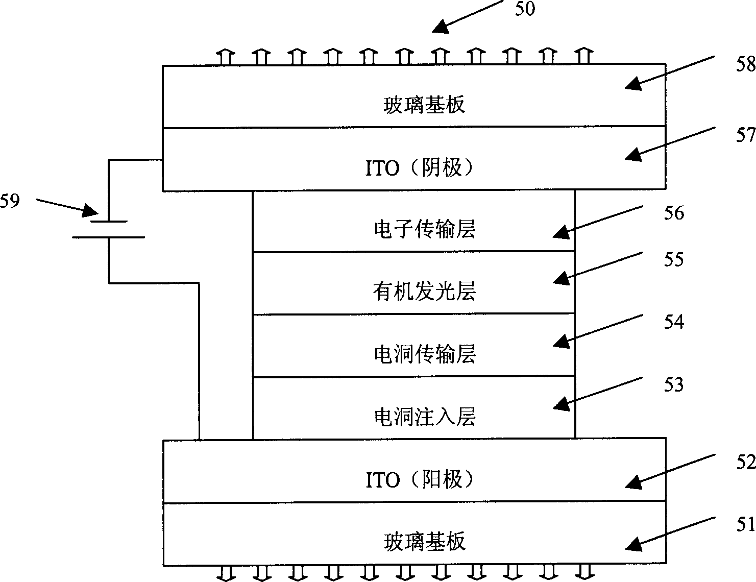
[0021] Please refer to Fig. 3, the double-sided display organic electroluminescent (Organic Light-Emitting Diode; OLED) device 50 of the present invention includes at least one transparent conductive glass (Indium-Tin Oxide; ITO) anode 52, one is opposite to this transparent ITO anode The transparent ITO cathode 57, and the organic light emitting layer (Emitting Layer; EML) 55 disposed on the ITO anode 52 and the ITO cathode 57.
[0022] The double-sided display OLED device 50 further includes a hole injection layer (Hole Injecting Layer; HIL) 53 and a hole transporting layer (Hole Transporting Layer; HTL) 54 disposed between the ITO anode 52 and the organic light-emitting layer 55, Wherein the hole injection layer 53 is adjacent to the ITO anode, the hole transport layer is adjacent to the organic light emitting layer 55; the electron transporting layer (Electron Tr...
PUM
 Abstract
Description
Claims
Application Information
 - Generate Ideas
- Intellectual Property
- Life Sciences
- Materials
- Tech Scout
- Unparalleled Data Quality
- Higher Quality Content
- 60% Fewer Hallucinations
Browse by: Latest US Patents, China's latest patents, Technical Efficacy Thesaurus, Application Domain, Technology Topic, Popular Technical Reports.
© 2025 PatSnap. All rights reserved.Legal|Privacy policy|Modern Slavery Act Transparency Statement|Sitemap|About US| Contact US: help@patsnap.com