

Brush, commutator, and commutator device
A technology of rectifier equipment and commutator, which is applied to circuits, current collectors, electrical components, etc., and can solve the problems of difficulty in further improving rectification and durability.
- Summary
- Abstract
- Description
- Claims
- Application Information
AI Technical Summary
Problems solved by technology
Method used
Image

Examples
no. 1 example
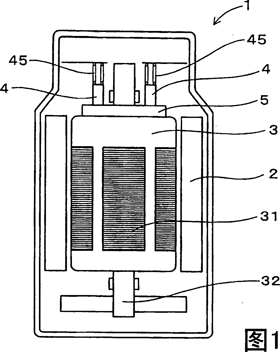
[0034] 1 and 2, a brush 4 and a commutator 5 of the first embodiment are used for a DC motor as a rotary electric machine. The DC motor 1 has a stator 2 and a rotor 3 , wherein the stator 2 is provided with permanent magnets or field coils, and the rotor 3 is provided with a plurality of armature windings 31 . A pair of brushes 4 are provided on the stator 2 to supply direct current. The commutator 5 is connected to the rotor shaft 32 of the rotor 3 . The commutator 5 has a plurality of commutator segments 6 which are connected to armature windings 31 respectively, as shown in FIGS. 4 and 5 .
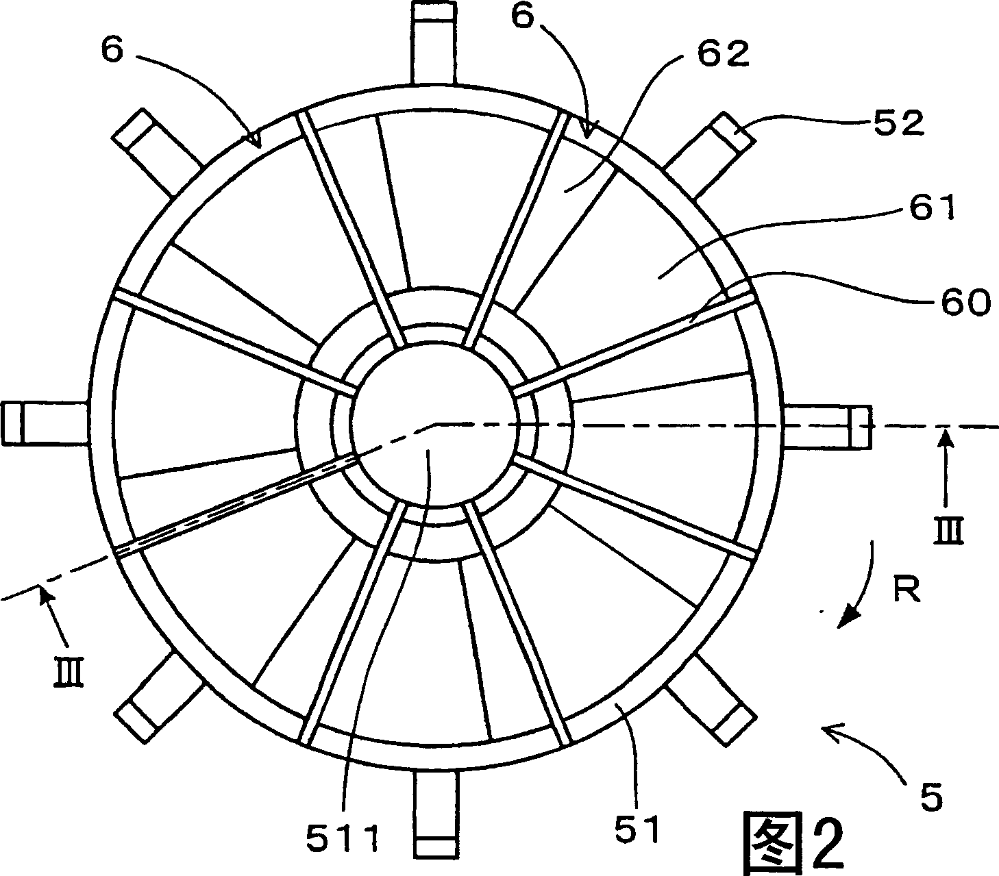
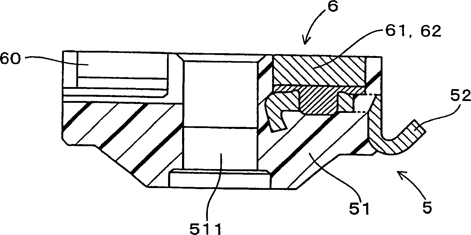
[0035] As shown in FIGS. 2 and 3 , the commutator 5 is of a flat type and placed on the axial end surface of the rotor 3 so as to be in contact with the brush 4 . Specifically, the commutator segments 6 are mounted on a disc-shaped resin body member 51 . The commutator segments 6 extend radially from the center 511 of the resin body member 51 . In addition, gaps 60 are formed betwee...
no. 2 example
[0054] Referring to Figures 6 and 7, the DC motor 1 of the second embodiment has a pair of brushes 4, each of which is composed of two resistive layers, and the commutator 5 has a plurality of commutator segments 6, each commutator segment Consists of a single layer. Specifically, each brush 4 has a low-resistance layer 41 made of a low-resistance material and a high-resistance layer 42 made of a high-resistance material, wherein the high-resistance material has a higher resistivity than the The resistivity of a low-resistance material.
[0055] The low resistance material contains carbon material and binder. The high-resistance material contains a carbon material, a binder, and boron nitride as an inorganic substance. Here, the mixing ratio of boron nitride is higher than 20wt% with respect to the total weight of the high resistance material.
[0056] The DC motor 1 of the second embodiment is used in a fuel pump of a vehicle, and the rotor 3 of the DC motor 1 rotates in t...
no. 3 example
[0069] An example of the manufacturing method of the commutator 5 of the first embodiment and the brush 4 of the second embodiment will be described below.
[0070] The manufacturing steps of the commutator sheet 6 and the brush 4 with two resistance layers 41, 42, 61, 62 are as follows:
[0071] First, as a method for producing a high-resistance material, carbon powder such as graphite (for example, 20 wt% of natural graphite powder with an average particle diameter of 30 μm) and inorganic powder such as boron nitride (such as 75 wt% of hexagonal boron nitride powder, The average particle size thereof is 10 μm) mixed with each other. Then, novolac resin (eg, weight ratio: 15) is added as a binder into the mixed powder (weight ratio: 100), wherein the novolac resin is dissolved in methanol solution (eg, weight ratio: 30). In addition, the mixing is performed with a mixer, and thus a mixed material is produced.
[0072] After that, the mixed material was dried in a drier to e...
PUM
| Property | Measurement | Unit |
|---|---|---|
| Resistivity | aaaaa | aaaaa |
| Length | aaaaa | aaaaa |
| Diameter | aaaaa | aaaaa |
Abstract
Description
Claims
Application Information