Ion generating element, ion generator, and electric device
What is Al technical title?
Al technical title is built by PatSnap Al team. It summarizes the technical point description of the patent document.
An ion generating device and ion generating technology, which are applied in electrical components, household refrigeration devices, corona discharge devices, etc., can solve problems such as lack of description, and achieve the effects of improving reliability and suppressing neutralization.
Active Publication Date: 2006-06-21
SHARP KK
View PDF9 Cites 20 Cited by
Summary
Abstract
Description
Claims
Application Information
AI Technical Summary
This helps you quickly interpret patents by identifying the three key elements:
Problems solved by technology
Method used
Benefits of technology
Problems solved by technology
As a high-voltage power supply, it is described that a diode is arranged at both ends of the electrodes, and a negative potential pow
Method used
Image
Click on the blue label to locate the original text in one second.
Reading with bidirectional positioning of images and text.
Examples
Embodiment Construction
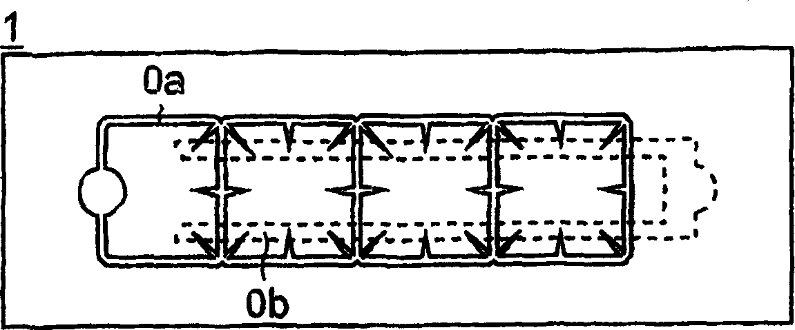
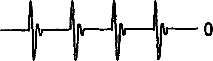
[0056] The ion generating device of the present invention eliminates and effectively releases the generated bipolar ions into the space in order to suppress the neutralization of positive ions and negative ions generated near the electrodes of the ion generating element, instead of using a single ion generating element with Instead of alternately generating positive ions and negative ions in a predetermined period, a plurality of ion generating elements are used to individually generate positive ions and negative ions and release each independently into the chamber (hereinafter referred to as the independent ion releasing method).
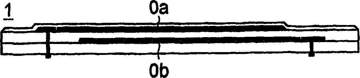
[0057] Before adopting the above-mentioned independent ion emission method, the following basic experiments were carried out first. In addition, as the form of the ion generating element used in this experiment, although the structure of needle-shaped electrodes can be adopted, here, it is conceivable to use a discharge electrode provided on the sur...
PUM
Abstract
The ion generating element (10) of the present invention is constituted by: having at least one first discharge part (12) for generating positive ions and one first discharge part (12) for generating negative ions each installed or printed on one dielectric (11). 2 discharge part (13), the 1st, the 2nd discharge part (12), (13) will be arranged on the 1st, the 2nd discharge electrode (12a), (13a) on the surface of the dielectric (11) and be embedded in the dielectric The first and second induction electrodes (12b) and (13b) inside (11) are formed as a pair, respectively, and are arranged independently and separated from each other on the same plane of the dielectric (11). With such a structure, neutralization of generated ions can be suppressed, positive and negative ions can be efficiently released, and ion generation efficiency can be further improved.
Description
technical field [0001] The present invention relates to an ion generating element capable of decomposing bacteria, fungi, harmful substances, etc. floating in the air by emitting positive ions and negative ions in space, an ion generating device, and electrical equipment equipped with the device. In addition, as an example corresponding to the above-mentioned electrical equipment, it is mainly possible to enumerate electrical equipment installed in enclosed spaces (inside homes, rooms in buildings, hospital wards and operating rooms, inside cars, inside airplanes, inside ships, inside warehouses, and refrigerators). Air conditioners, dehumidifiers, humidifiers, air cleaners, refrigerators, fan heaters, microwave ovens, washing and drying machines, vacuum cleaners, sterilizers, etc. used in warehouses, etc. Background technique [0002] Generally, in closed rooms with little ventilation such as offices and meeting rooms, when there are many people in the...
Claims
Application Information
Patent Timeline
Application Date:The date an application was filed.
Publication Date:The date a patent or application was officially published.
First Publication Date:The earliest publication date of a patent with the same application number.
Issue Date:Publication date of the patent grant document.
PCT Entry Date:The Entry date of PCT National Phase.
Estimated Expiry Date:The statutory expiry date of a patent right according to the Patent Law, and it is the longest term of protection that the patent right can achieve without the termination of the patent right due to other reasons(Term extension factor has been taken into account ).
Invalid Date:Actual expiry date is based on effective date or publication date of legal transaction data of invalid patent.