Parallel scanning type focus ultrasonic sound field fault imaging hydrophone system

A focused ultrasound and tomographic imaging technology, applied in ultrasonic/sonic/infrasonic diagnosis, measurement of ultrasonic/sonic/infrasonic, sonic diagnosis, etc., can solve problems such as the inability to achieve rapid measurement, and achieve the effect of improving work efficiency

Inactive Publication Date: 2006-06-28
SHANGHAI JIAO TONG UNIV
View PDF1 Cites 5 Cited by
  • Summary
  • Abstract
  • Description
  • Claims
  • Application Information

AI Technical Summary

Problems solved by technology

"Its shortcoming is: since the device is a manual single-point measurement of the sound field, it is difficult to find the maximum sound pressure
However, according to the national standard of high-intensity focused ultrasonic sound output, sound field scanning is necessary. Automatic sound field scanning generally uses GPIB bus for data collection, a

Method used


Image

  • Parallel scanning type focus ultrasonic sound field fault imaging hydrophone system

Examples


Embodiment Construction

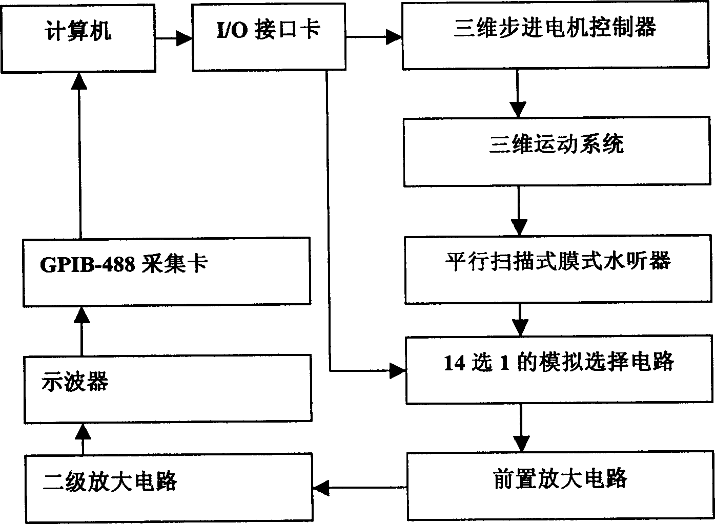
[0013] like figure 1 As shown, the present invention includes: a signal acquisition module, a motor control and motion module, a parallel scanning membrane hydrophone, a computer, the signal acquisition module is connected to the signal line of the parallel scanning membrane hydrophone, and the computer is connected to the signal acquisition module. The computer is connected with the motor control module at the same time, and the motor control and motion module is connected with the parallel scanning membrane hydrophone.

[0014] The parallel scanning membrane hydrophone adopts polyvinylidene fluoride piezoelectric film.

[0015] Described PVDF thin film, its diameter is 10cm, and the lower surface of film is coated with one deck silver layer, as signal grounding end, and the other side of film is coated with parallel silver wire, and every silver wire width is 0.5mm, and the width between lines is 2.5mm, a total of 14 pieces.

[0016] The motor control and motion module inc...


PUM

PropertyMeasurementUnit
Diameteraaaaaaaaaa
Widthaaaaaaaaaa

Abstract

A sonar system for parallel scan type focused ultrasonic-field tomography is composed of signal acquisition module, motor controlling and moving module, parallel scan membrane type sonar device, and computer.

Description

technical field [0001] The invention relates to a hydrophone system in the technical field of measuring equipment, in particular to a parallel scanning focused ultrasonic sound field tomography hydrophone system. Background technique [0002] Due to the continuous development of medical ultrasound, the safety of the acoustic output of ultrasonic equipment is very important. The detection of acoustic output requires a corresponding detection sensor - hydrophone. The current hydrophone mainly includes needle type and membrane type hydrophone. They both measure the sound pressure waveform at a point in space. Medical ultrasound mainly includes B-ultrasound and high-intensity focused ultrasound. They all need to measure the sound field of an area. Generally, the method of hydrophone scanning is used to obtain the sound pressure distribution of a scanning plane. The scanning step is determined by the frequency of the ultrasonic wave. For high-intensity focused ultrasound, you ca...

Claims


Application Information

Patent Timeline
IPC IPC(8): A61B8/00G01H7/00
Inventor 夏荣民
Owner SHANGHAI JIAO TONG UNIV
Why Eureka
Try Eureka