Rear projection display

A video display and video technology, which is applied in the direction of image reproducer of projection device, projection device, color TV, etc., can solve the problems of inability to achieve high brightness, inability to unitize, and inability to display panel distances, etc., and achieves improved assembly. performance and assembly accuracy

Inactive Publication Date: 2006-06-28
SANYO ELECTRIC CO LTD
View PDF4 Cites 5 Cited by
  • Summary
  • Abstract
  • Description
  • Claims
  • Application Information

AI Technical Summary

Problems solved by technology

[0003] However, in the technique of the former patent document, since the video light of each color is synthesized by a dichroic prism, the video light of a certain wavelength band is cut off and high brightness cannot be achieved, and there are various disadvantages.
In addition, in the technique described in the latter patent document, it is necessary to separate the white light from one light source, and in this color separation, there is a disadvantage that the distances from the light source to the liquid crystal display panel cannot be made equal for all colored lights.
In addition, the projection system of each color video light is not independent in the form of including a light source, so it cannot be unitized (integrated) in the form of a light source included in the projection system of each color video light. In addition, it is difficult to project the various colors of video light system for optimal design or optimal control of light sources

Method used


Image

  • Rear projection display
  • Rear projection display
  • Rear projection display

Examples


Embodiment Construction

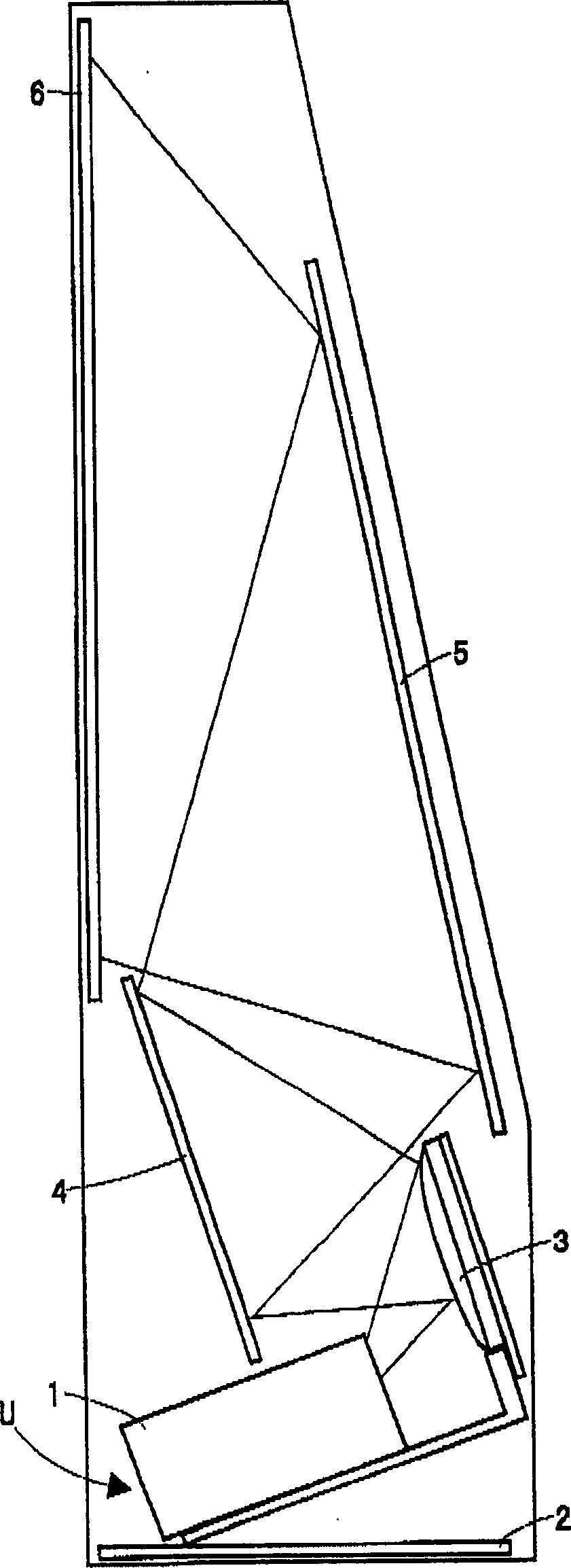
[0028] Compare below Figure 1 to Figure 7 , the rear projection type video display device according to the embodiment of the present invention will be described.

[0029] figure 1 It is a side view showing the internal structure (optical system) of the rear projection type video display device according to the embodiment of the present invention. In the lower structural portion of the chassis 2 of the rear projection video display device, a position adjustment mechanism (not shown) is provided, and the video light generation optical unit U is attached to the position adjustment mechanism. The video light generating optical unit U is composed of a video light generating optical system 1 and three aspheric mirrors 3 . The video lights of each color emitted from the video light generating optical system 1 are respectively reflected by the aspheric mirror 3 . Furthermore, a reflection mirror 4 is provided at a position where the color video light reflected by the aspheric mirr...


PUM


Abstract

The present invention provides an illuminating device and a projection type video display device that do not require a dichroic prism, and that generate systems for each color of video light independently, thereby enabling optimization of each generating system and improvement in assembly. Each video light projection unit is composed of an LED array, a columnar integrator, a liquid crystal display panel and a projection lens. The projection optical axes of the projection lenses in each video light unit are parallel to each other. The red video light projection unit has an LED array that emits light in the red wavelength band, the green video light projection unit has an LED array that emits light in the green wavelength band, and the blue video light projection unit has an LED array that emits light in the blue wavelength band. The video lights of various colors obtained through the liquid crystal display panel are magnified and projected by the projection lens, and projected on the screen, so that the video lights of various colors overlap on the screen to display full-color video.

Description

technical field [0001] The present invention relates to a rear projection type video display device. Background technique [0002] There is a projection type video display device (JP-A-2004-220015), which has three color light sources that respectively emit light of three primary colors, and light modulation of each color light from each color light source through a light valve, and a dichroic prism (dichroic prism) synthesizes video lights of various colors obtained through the light modulation, and projects the full-color video light obtained through the synthesis through a projection lens. In addition, it has also been proposed that each color light obtained by color-separating white light from one light source is light-modulated by a liquid crystal display panel, and that each color video light obtained by the light modulation is projected through three projection lenses, A liquid crystal rear projection television in which video lights of various colors are superimpose...

Claims


Application Information

Patent Timeline
Patent Type & Authority Applications(China)
IPC IPC(8): G02B27/18G02F1/13H04N9/31
CPCG03B21/10G03B21/16G03B21/28H04N9/3105H04N9/3141
Inventor 池田贵司三轮孝司村田治彦金山秀行
Owner SANYO ELECTRIC CO LTD
Why Eureka
Try Eureka