Piping bag, blank for manufacturing a piping bag and method of manufacturing a piping bag

A technology for piping bags and blanks, applied in the directions of bags, household components, flexible coverings, etc., can solve the problems of difficult handling of piping bags, and achieve the effect of being easy to hold and reducing slippage.

Active Publication Date: 2006-06-28
KEE PLASTICS
View PDF1 Cites 3 Cited by
  • Summary
  • Abstract
  • Description
  • Claims
  • Application Information

AI Technical Summary

Problems solved by technology

[0004] A related problem with existing single-use piping bags is that they are difficult to dispose of during production and in connection with dispensing operations

Method used


Image

  • Piping bag, blank for manufacturing a piping bag and method of manufacturing a piping bag
  • Piping bag, blank for manufacturing a piping bag and method of manufacturing a piping bag
  • Piping bag, blank for manufacturing a piping bag and method of manufacturing a piping bag

Examples


Embodiment Construction

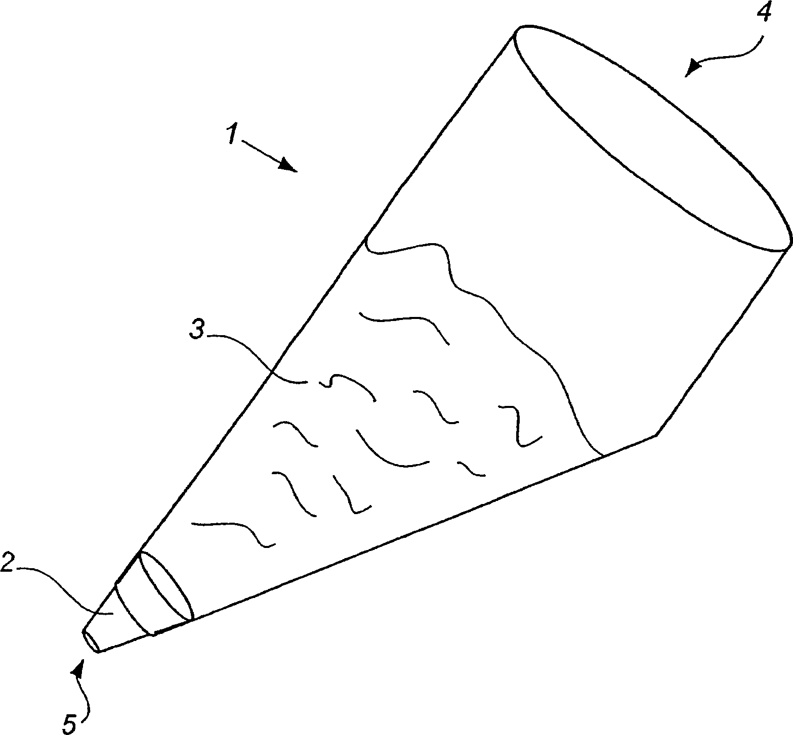
[0022] figure 1 Shown is a piping bag 1 provided with a spout 2 at its dispensing hole 5 and filled with a flowable paste 3 through an open end 4 . When the open end 4 of the piping bag 1 is closed, eg folded and squeezed, the flowable paste 3 can be dispensed through the nozzle 2 .

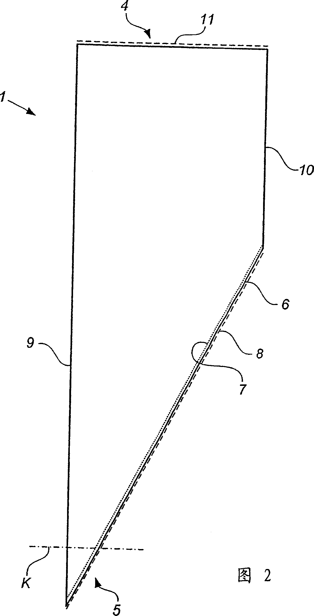
[0023] Referring to Figure 2, the piping bag 1 is formed from polymeric tubing, preferably polyolefin plastic, such as polyethylene, polypropylene or the like. When unfilled, as shown in Figure 2, the piping bag 1 is basically a two-dimensional extension in the shape of two parallel creases formed by the flattened polymer tube at the edges 9, 10 and a cross-edge 9 and 10 are defined by the oblique connecting line 7. The isolation mark 8 extends parallel to the connection line 7, and the isolation mark 8 is implemented in a manner known to those skilled in the art, such as through perforation. At the open end 4 of the piping bag 1 , a spacer marker 11 extends perpendicularly to the edges 9 , 10...


PUM


Abstract

The invention discloses a disposable piping bag (1) comprising a polymer film container. Piping bags are essentially formed from a thin-walled polymer tube, the outwardly facing surface of the piping bag being provided with a surface structure.

Description

technical field [0001] The present invention relates to a single-use piping bag as defined in the preamble of claim 1 , and more particularly to a single-use piping bag for handling food products. Background technique [0002] Piping bags are mainly used for decorating pastries, confectionery or sticky foods, semi-liquid or semi-fluid doughs such as whipped cream, marzipan, dough, cream cheese, sugar dough or similar materials. Piping bags can also be used for other purposes, such as application to stickies, cement, plaster of paris, molding compound or the like. [0003] A disposable piping bag is shown in US Pat. No. 3,157,312. These piping bags consist of two layers of polymer film formed into a plastic bag and welded together along the edges of the bag. One corner of the piping bag is adapted to accommodate a generally tapered nozzle through which the paste contained in the piping bag can be expelled. The nozzle has a selectable profile so that the extruded stick of p...

Claims


Application Information

Patent Timeline
Patent Type & Authority Applications(China)
IPC IPC(8): A23G3/28A21C15/00A23G3/02B65D37/00
CPCA21C15/005A23G3/2015A23G3/2023A23G3/28B29C65/02B29C66/1122B29C69/001B29C2793/0045B29L2023/001B29L2031/7128B65D31/18B65D65/38B29C66/4312B29C66/43129B29C66/72341B29C66/73161B29C48/10B29C48/13B29C48/0018B29C48/0019
Inventor 阿伦·埃杰布拉德
Owner KEE PLASTICS
Why Eureka
Try Eureka